An LED dot matrix display consists of a matrix of LED’s arranged in a rectangular configuration. The desired character or graphics can be displayed by switching ON /OFF a desired configuration of LED’s. Common display configurations available are 7×5, 8×8, 7×15, etc. LED dot matrix can be used in simple display applications where the resolution is not a big concern. The figure below shows the arrangement of LEDs in a typical 7×5 dot matrix display.Any individual LED or a group of LEDs in the matrix can be activated by switching the required number of rows and columns.

Fig.1: Circuit Diagram of Dot Matrix LED Display
Working
Light-emitting diodes (LEDs) provide a cheap and convenient way to display information electronically. LEDs are tiny light sources that are illuminated solely by the movement of electrons in semiconducting materials. They emit light when forward-biased, fit easily into an electrical circuit, and are durable. LEDs are often arranged in patterns to display information. The seven-segment configuration of an LED arranged in the form of the digit 8 can be restrictive in that it does not adequately allow the display of some alphanumeric characters. By contrast, the versatility of a dot-matrix arrangement allows an LED unit to display complicated shapes.

Fig. 2: Representational Image of Dot Matrix LED Display
Stable Character
This diagram is for practice and programming, wants you have it working you can put transistors and resistors on. Here we put the letter A on the display as you can see in video, using a breadboard.
Let’s understand how it works. First connect row and column to the microcontroller PORT P3 and PORT P2 respectively. Then by using programing sends data to first column and at same time sends data to row and then after some milli-seconds change the column and send data to row again. And do this till last column and then repeat it again and again around speed of greater then 20 frame per second.

Fig. 3: Image displaying stable character formation on Dot Matrix LED Display
Moving Character
How to scroll a character across the display? The trick is to build one character on the display by scanning the columns very fast, and let say each 20 times (20 frames) scroll it one position to the left, this will give the effect of a walking text across the dot-matrix display. So first build one frame, repeat this 20 times, and after that, read the data one address later, if you do this 5 times (5 columns) the character scroll from right to left from the display. (The refresh goes so fast that your brain can’t keep up, and what you see is the A scrolling over the display

Fig. 4: Image displaying animation of characters on Dor Matrix LED Display
Moving String
And in third part of the code, here is displaying “Dot Matrix Display By Saddam Khan”. The working of displaying string of character on Dot matrix display is also same as last paragraph.
Components Used
89S52 microcontroller
A microcontroller is a small computer on a single integrated circuit containing a processor core, memory, and programmable input/output peripherals. The Program memory in the form of NOR flash or OTP ROM is also often included on chip, as well as a typically small amount of RAM. Microcontrollers are designed for embedded applications, in contrast to the microprocessors used in personal computers or other general purpose applications.
Fig 1.3: Microcontroller (AT8051)

Fig. 5: Image of 8051 Microcontroller
Dot Matrix LED display
Light emitting diodes aligned in a form of matrix constitute a dot matrix display. It is commonly used to display time, temperature, news updates and many more on digital billboards. Dot Matrix Display is manufactured in various dimensions like 5×7, 8×9, 128×16, 128×32 and 128×64 where the numbers represent LEDs in rows and columns, respectively.
Arrangement of the LEDs in the matrix pattern is made in either of the two ways: row anode-column cathode or row cathode-column anode. In row anode-column cathode pattern, the entire row is anode while all columns serve as cathode and vice-versa pattern is there in row cathode-column anode. LED wafers are glued to the bottom of the segments and glow when powered ON. The interesting part is that 35 LEDs are controlled by using a combination of 14 pins. Conductor tracks are laid all over the board to power each LED. Let’s proceed to know in depth about how a dotmatrix display works.

Fig. 6: Internal Circuit Diagram and Image of Dot Matrix LED Display
Project Source Code
###


#include<reg51.h>
char col[5]={0x01,0x02,0x04,0x08,0x10};
char raw[5]={0xc1,0xb7,0xb7,0xc1,0xff};
void delay(unsigned int a)
{
 unsigned int i,j;
 for(i=0;i<a;i++)
 for(j=0;j<500;j++);
}
void main()
{
 unsigned int l;
 P2=0x00;
 P3=0x00;
 while(1)
 {
 for(l=0;l<5;l++)
 {
  P2=col[l];    // column
  P3=raw[l];    // row
  delay(1);
 }
}
}


Moving Char


#include<reg51.h>
char col[5]={0x01,0x02,0x04,0x08,0x10};
char raw[5]={0xc1,0xb7,0xb7,0xc1,0xff};
void delay(unsigned int a)
{
 unsigned int i,j;
 for(i=0;i<a;i++)
 for(j=0;j<1275;j++);
}
void main()
{
 unsigned int i,j,k,l;
 P2=0x00;
 P3=0x00;
 while(1)
 {
 for(l=0;l<5;l++)
 {
 for(j=0;j<30;j++)
 {
  for(i=0;i<5;i++)
  {
  if(k==5){k=0;}
  P2=col[i];    // column
  P3=raw[k];    // row
  delay(1);
  k++;
 }
}
 k=5-l;
}
}
}


Moving String


#include<reg52.h>
void delay()
{
 unsigned char j;
 for(j=0;j<100;j++);
}
 unsigned char col[6]={0x10,0x08,0x04,0x02,0x01,0x20};
 unsigned char idata dot[236]={
 0xff,0xff,0xff,0xff,0xff,   //
 0xff,0xff,0xff,0xff,0xff,   //
 0x81,0xbd,0xbd,0xc3,0xff,   //d
 0xc3,0xbd,0xbd,0xc3,0xff,    //o
 0xff,0xbf,0x81,0xbf,0xff,    //t
 0xff,0xff,0xff,        //
 0x81,0xcf,0xcf,0x81,0xff,   //m
 0xc1,0xb7,0xb7,0xc1,0xff,   //a
 0xff,0xbf,0x81,0xbf,0xff,    //t
 0x81,0xb7,0xb3,0xcd,0xff,    //r
 0xff,0xbd,0x81,0xbd,0xff,    //i
 0x99,0xe7,0xe7,0x99,0xff,   //x
 0xff,0xff,0xff,           //
 0x81,0xad,0xad,0xd3,0xff,    //b
 0x8d,0xf3,0xf7,0x8f,0xff,    //y
 0xff,0xff,0xff,                 //
 0xdb,0xad,0xb5,0xdb,0xff,   //s
 0xc1,0xb7,0xb7,0xc1,0xff,   //a
 0x81,0xbd,0xbd,0xc3,0xff,   //d
 0x81,0xbd,0xbd,0xc3,0xff,   //d
 0xc1,0xb7,0xb7,0xc1,0xff,   //a
 0x81,0xcf,0xcf,0x81,0xff,   //m
 0xff,0xff,                //
 0x81,0xe7,0xdb,0xbd,0xff,   //k
 0x81,0xf7,0xf7,0x81,0xff,   //h
 0xc1,0xb7,0xb7,0xc1,0xff,   //a
 0x81,0xcf,0xf3,0x81,0xff   //n
 };
void main()
{
 unsigned char k,l,m=0,n;
 while(1)
 {
  for(n=0;n<100;n++)
  {
   for(k=0;k<6;k++)
   {
    P2=col[k];
   P3=dot[l];
   delay();
   l++;
   if(l==126){l=0;}
  }
  l=m;
  if(m==126){m=0;}
  }
 m++;
 l=m;
 }
}

###
Circuit Diagrams
| Circuit-Diagram-8051-Microcontroller-Based-Dot-Matrix-LED-Display-Controller | 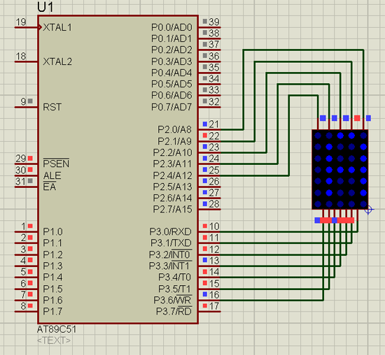 |
| Circuit-Diagram-8051-Microcontroller-Based-Dot-Matrix-LED-Display-Controller_0 | 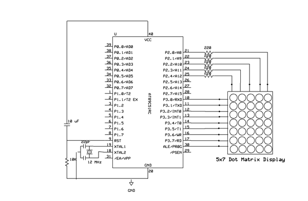 |
Project Video
Filed Under: Electronic Projects
Filed Under: Electronic Projects

Questions related to this article?
👉Ask and discuss on Electro-Tech-Online.com and EDAboard.com forums.
Tell Us What You Think!!
You must be logged in to post a comment.