1) How to Interface LED to ARM7 Microcontroller (LPC2148)?
Everybody knows that LED is an output device. When you want to interface LED to ARM7, you need three things. First is the content of FIO0DIR register of ARM7. This register will provide output direction by writing “1” and input direction by writing “0” in the bit.
Second thing is that for sending “1” signal on Port 0.21 we have to use FIO0SET register. Suppose I want to send “1” signal on 0th line of Port0. Then I can load FIO0SET=0x1; value considering the fact that FIO0SET is 32 bit register.
Third thing is the content of FIO0CLR register. Here is the catch, to clear I/O line or Port line of ARM7 we have to use “1” only. We have to write this “1” in FIO0CLR register.

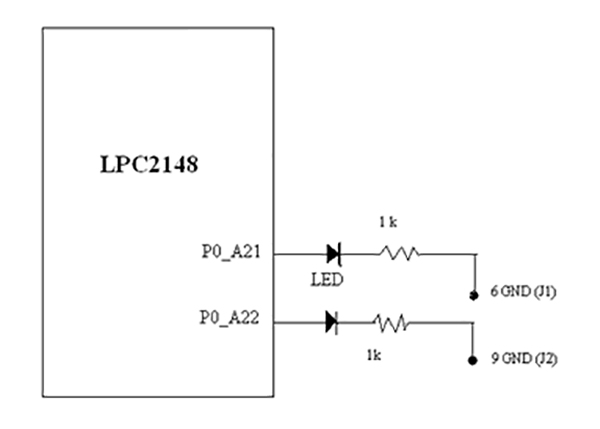
Fig. 1: Circuit Diagram of LPC2149 ARM Controller and LED Interfacing Prototype to test Digital Output
Fig 1: Interfacing of LED to Port P0.21 and P0,22 of LPC2148
Procedure:
1.1 Create new project, named as led in Keil Ver 4, and select device LPC2148 from device list.
1.2 Write the program Listing P1-1 led.c as source program. Add led.c source program to project by right clicking “Source Group “ on Project window. Include startup.s file from Keil cross compiler environment. Select output file as HEX file from “Options of Target” menu and build the project. Keil will create HEX file by project name that is led.hex . Download this HEX file to flash memory of LPC2148 through FlashMagic software.
1.3 Run the program. Observe the operation of LED at P0.21 and P0.22
Important function in this program.
Ø init increases processing speed up to 5 times from 12 MHZ( main crystal) to 60MHZ with PLL x5 . After executing this function, CCLK increases to 60 MHz.
Ø delay_ms Delay function in millisecond unit. This function will refer to 60MHz CCLK and init function.
Ø Listing:
#include “lpc214x.h” // Header file for Phillips LPC2148 controller
#define LED1_ON FIO0CLR = 0x00200000 // Red led 0.21 on
#define LED1_OFF FIO0SET = 0x00200000 // Red led 0.21 off
#define LED2_ON FIO0CLR = 0x00400000 // Red led 0.22 on
#define LED2_OFF FIO0SET = 0x00400000 // Red led 0.22 off
//————————————————————————————————//
void init()
{
PLL0CFG=0x24; // MSEL = 4,PSEL = 2
PLL0FEED=0xAA; // Feed process
PLL0FEED=0x55;
PLL0CON=0x1;
PLL0FEED=0xAA; // Feed process
PLL0FEED=0x55;
while(!(PLL0STAT & 0x400)) ; // Wait until PLL Locked
PLL0CON=0x3; // Connect the PLL as the clock source
PLL0FEED=0xAA; // Feed process
PLL0FEED=0x55;
MAMCR=0x2; // Enabling MAM and setting number of clocks used for Flash memory fetch (4 cclks in this case)//
MAMTIM=0x4;
VPBDIV=0x02; // PCLK at 30 MHz
}
//—————————delay routine——–//
void delay_ms(long ms) // delay 1 ms per count @ CCLK 60 MHz
{
long i,j;
for (i = 0; i < ms; i++ )
for (j = 0; j < 6659; j++ );
}
//———————————- Main Program —//
void main()
{
init(); // Initialize the system
SCS = 0x03; // select the “fast” version of the I/O ports
FIO0DIR = 0x00600000; // Config. pin P0.22 and P0.21 as output
while (1) // Infinite loop
{
LED1_ON; // Led at P0.21 ON
LED2_OFF; // Led at P0.22 OFF
delay_ms(500); // Delay 500 ms
LED2_ON; // Led at P0.22 ON
LED1_OFF; // Led at P0.21 OFF
delay_ms(500); // Delay 500 ms
}
Note: You can use 3 mm LED for this experiment. I have tested this experiment on P0.21 and 0.22 ports of LPC2148. Assuming that you have Keil cross compiler to run this program, it is advised to use proper LPC214x.h header file.
2) How to use External Interrupt of ARM7 (LPC2148)
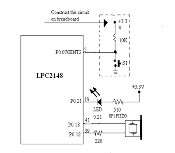
In this code, we are assuming that you have ARM7 board where at least one external switch is connected to 7th line of Port 0 of Lpc2148. There is an LED also which is connected to P0.21 of Lpc2148. When you burn HEX file in the lpc2148 microcontroller, use flash magic software and reset Lpc2148 microcontroller.
After pressing Switch, LED should blink. I have tested this code on “Made in India” LPC2148 board.

Fig. 2: Circuit Diagram of LPC2149 ARM Controller and Switch Interfacing Prototype for Digital Input
Procedure :
3.1Build new project, with the name ext_int2
3.2 Write the program Listing P3-1. Compile to ext_int2.hex and download it to microcontroller.
3.3 Run program. Try to press switch at P0.07 or EINT2 port pin. Observe the operation of LED at P0.21 and Piezo.
3.4 Switch P0.07 is pressed to control LED at P0.21 and generate sound for informing about the occurrence of external interrupt.
Check for code in above code tab.
Project Source Code
###//Program toListing:
// Program : Example for EINT2 (External interrupt2)
// Description : Test interrupt from switch press display by LED at P0.21 toggle and sound beep
// Frequency : Crystal 12 MHz at PLL 5x(CCLK = 60 MHz),PCLK = 30 MHz
// Filename : ext_int2.c
// C compiler : Keil CARM Compiler
//------------------------------------------------------------------------------------------------//
#include "lpc214x.h" // Header file for Phillips LPC2148 controller
#include "sound.h" // Header file for Phillips LPC2148 controller
//---------------------------- Function for Initial system clock --------------------------------//
void init()
{
PLL0CFG=0x24; // MSEL = 4,PSEL = 2
PLL0FEED=0xAA; // Feed process
PLL0FEED=0x55;
PLL0CON=0x1;
PLL0FEED=0xAA; // Feed process
PLL0FEED=0x55;
while(!(PLL0STAT & 0x400)) ; // Wait until PLL Locked
PLL0CON=0x3; // Connect the PLL as the clock source
PLL0FEED=0xAA; // Feed process
PLL0FEED=0x55;
MAMCR=0x2; // Enabling MAM and setting number of clk used for Flash memory fetch (4 cclks in this case)//
MAMTIM=0x4;
VPBDIV=0x02; // PCLK at 30 MHz
}
//---------------------------- Interrupt service routine for EINT2 -------------------------------//
void isr_int2(void) __irq
{
beep(); // Sound beep 1 time
FIO0PIN ^= (1<<21); // Toggle LED at P0.21
EXTINT |= 0x4; // Clear interrupt flag EINT2
VICVectAddr = 0; // Acknowledge Interrupt
}
//---------------------------------- Main Program ------------------------------------------------//
//------------------------------------------------------------------------------------------------//
void main()
{
init(); // Initialize the system
SCS = 0x03; // select the "fast" version of the I/O ports
FIO0DIR |= (1<<21); // Config. output P0.21 connect LED
FIO0SET |= (1<<21); // OFF LED
EXTMODE |= 0x4; // EINT2 Edge sensitive detection(Falling edge in this program)
PINSEL0 = 0xC000; // Enable EINT2 at P0.7
VICVectAddr0 = (unsigned)isr_int2; // Register Interrupt service routine name
VICVectCntl0 = 0x20 | 16; // EINT2 Interrupt
VICIntEnable |= 1 << 16; // Enable EINT2 Interrupt
while(1); // Infinite loop
}
Important function in this program.
Ø beep : Generate beep sound one time. This function is added in sound.h libray.
Ø syntax: void beep( )
Note: Instead of LED, you can also connect a small speaker. That’s why beep function is there. Ultimately Beep is sending “1” and “0”
Note: If you are not having sound.h file then you can type it and save in project directory.
//------------------------------------------------------------------------------------------------//
// Program : Library for generate sound
// Description : Library for generate easy sound
// Frequency : Crytal 12 MHz at PLL 5x(CCLK = 60 MHz),PCLK = 30 MHz
// Filename : sound.h
// C compiler : Keil Cross Compiler
//------------------------------------------------------------------------------------------------//
//------------------------------------------------------------------------------------------------//
//---------------------------- Function delay 100 us per count -----------------------------------//
//------------------------------------------------------------------------------------------------//
void delay_sound(long c) // Delay 100 us per count @ CCLK 60 MHz
{
long i,j;
for (i = 0; i < c; i++ )
for (j = 0; j < 660; j++ );
}
//------------------------------------------------------------------------------------------------//
//---------------------------- Function generate sound -------------------------------------------//
//------------------------------------------------------------------------------------------------//
void sound(int freq,int time)
{
int dt=0,m=0; // Keep value and
FIO0DIR |= 0x00003000; // Set P0.13 and P0.12 @ output
dt = 5000/freq; // Keep active logic delay
time = (5*time)/dt; // Keep counter for generate sound
for(m=0;m<time;m++) // Loop for generate sound(Toggle logic P0.12)
{
FIO0SET |= 0x00001000; // P0.12 = '1'
delay_sound(dt); // Delay for sound
FIO0CLR |= 0x00001000; // P0.12 = '0'
delay_sound(dt); // Delay for sound
}
}
//------------------------------------------------------------------------------------------------//
//---------------------------- Function generate sound beep default ------------------------------//
//------------------------------------------------------------------------------------------------//
void beep(void)
{
sound(600,100); // Generate sound default frequency
}
###
Filed Under: Electronic Projects


Questions related to this article?
👉Ask and discuss on EDAboard.com and Electro-Tech-Online.com forums.
Tell Us What You Think!!
You must be logged in to post a comment.