This article would give you a general idea about how to setup and interface any Bluetooth modem with your computer. There are many types of Bluetooth modems available in market, which vary in quality, cost, range, etc. Some of the well known Serial Bluetooth modems are AUBTM, BLUESMIRF, RN-41, HC-05 and HC-04.
I would be using the last one i.e. the cheap Chinese Bluetooth module. It has limited functions and it can only work in slave mode. (Remember: Two slave modules cannot directly communicate to each other so be careful when you buy them.) The top range modules have a facility to work in both MASTER and SLAVE modes. It is Class 3 module so it range is very low. (Class 2 has a range of 10 meters and Class 1 has a range of 100 meters.)
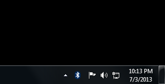
Step 1: Power ON the Serial Bluetooth Modem and also turn ON the Bluetooth on your computer. You should see the below icon at the right hand corner of your computer.
Step 2: Right-click on the Bluetooth Icon and you should see the below given option. Click on “Add a Device” option.

Once you click that option you computer initiates a Bluetooth connection and starts searching for any nearby Bluetooth enable devices.
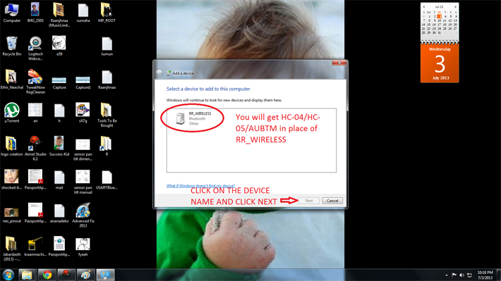
Step 3: You should next see this type of dialog box which will be loaded with the active Bluetooth devices in the surroundings. You should see something like”HC-04” or “HC-05” or “AUBTM” or some other similar names. Click on the device name and click “Next” then.
Note: I already renamed my Serial Bluetooth Modem to “RR_WIRELESS” so that’s what is appearing in the list there. Refer your modem’s datasheet to know how to rename the module’s Bluetooth Name.
Step 4: Next, the computer would ask you whether you want to create a pairing code or enter device’s pairing code or to pair without using code. Click on “Enter the device’s pairing code”. Generally, all modems would have a default pairing code (Even cheap Chinese modems). So you have no other alternative to pair the device with your computer.
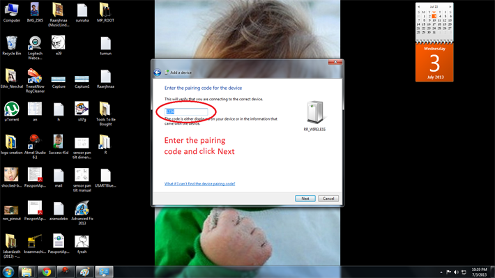
Step 5: Enter your device’s pairing code as shown below. Refer your modem’s datasheet to know the default pairing code of your device. It is generally “0000” or “1234”. In my case it was “1234”. Enter the code and click “Next”.

As soon as you click “Next” you should see notifications at your right hand corner saying “Device drivers being installed”.
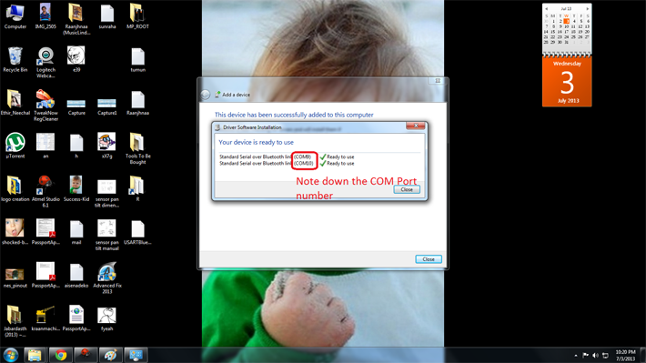
Step 6: If everything goes well in the end you should see a pop-up similar to one shown below. Note down the COM Port numbers since we’ll be using those only to establish future connections between your modem and your PC.
RUNNING THE DEMO PROJECT:
We are done with configuring the Serial Bluetooth Modem with the computer. Next we’ll see how to run the demo program.
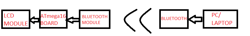
Block Diagram
BLOCK DIAGRAM:
Step 1: Burn the attached “demo.hex” file into your ATMega16 microcontroller using the necessary programmer and software.
Step 2: Connect the LCD module and Bluetooth modem to the Development Board. Note that TX pin of modem is connected to RX pin of the microcontroller and RX pin of modem to the TX pin of the controller.
Step 3: Now you’ll need Serial Communication software to communicate with the ATmega16 through Bluetooth. If you are a Windows XP user then you would have default software called “HyperTerminal” in your computer. But if you are a windows 7 user like me then you need a third party software. There are various free third party software solutions available in internet like RealTerm, Putty and TeraTerm. Or you can buy the HyperTerminal Private edition too.
Note: I’m using a Windows Form Application which I created myself using Visual Studio 2012. I will explain you how to make one by yourself in the next tutorial.
Whichever software you use, these would be the general steps to be followed while establishing the connections.
Turn ON the controller board and Bluetooth in your computer.
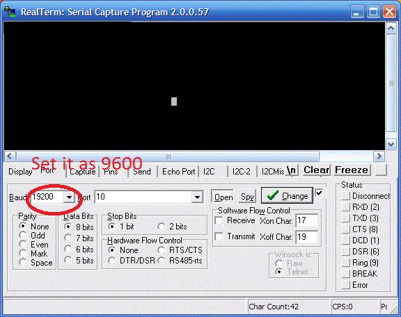
Open the Serial Port software. There would be many options and configuration settings. Don’t modify any of them unnecessarily. Just change the below given settings.
Go to the Port Tab and set it as follows.
Baud: 9600
Port: <The port we previously noted down during first time setup>
Data bits: 8
Parity: None
Stop bits: 1
Hardware Flow Control: None
The below image shows you a screenshot of the configurations .
Now type something on the screen and you should see the same text being displayed on the LCD also which is connected to the controller board.
Working of project code
|
Function Name
|
Purpose of the Function
|
|
LCDClear()
|
Clears the screen of the LCD display.
|
|
LCDWriteString(“<string>”)
|
Displays the <string> on the LCD display.
|
|
LCDWriteStringXY(x,y,”<string>”)
|
Goes to position x, y of the LCD display and displays the <string>
|
|
LCDData(x)
|
Displays the character stored in variable ‘x’ which is of “char” type.
|
|
LCDInit()
|
Initializes the LCD.
|
USART implementation code
|
Function Name
|
Purpose of the Function
|
|
BlueRdChar()
|
Reads the data available at RX pin of the controller. It waits till any data is available.
|
|
BlueWrChar(data)
|
Writes the character stored in variable “data” into USART line which in turn transmits it to TX pin of controller.
|
|
BlueInit(n)
|
Initializes the USART function with required baud rate set by the integer ‘n’
|
Working of Code (Algorithm)
Project Source Code
###
/** USARTBlue.c** Created: 7/1/2013 10:50:05 PM* Author: GANESH SELVARAJ*/#define F_CPU 16000000UL#include <avr/io.h>#include <inttypes.h>#include "lib/LCD/lcd.h"void BlueInit(uint16_t ubrr_value) //This function is used to initialize the USART at a given UBRR value{//Set Baud rateUBRRL = ubrr_value;UBRRH = (ubrr_value>>8);/*We Set Frame Format as>> Asynchronous mode>> No Parity>> 1 StopBit>> char size 8*/UCSRC=(1<<URSEL)|(3<<UCSZ0);//Enable The RX receiver and TX transmitterUCSRB=(1<<RXEN)|(1<<TXEN);}char BlueRdChar() // function used to read data from USART line. It waits till any data is available{while(!(UCSRA & (1<<RXC))){}return UDR;}void BlueWrChar(char data) // function writes the character in 'data' into USART and then transmits it to PC via TX line{while(!(UCSRA & (1<<UDRE))){}UDR=data;}void Waiting(int j) // simple delay function{uint8_t i;for(i=0;i<j;i++)_delay_ms(200);}int main(){char data;int i;/*First Initialize the USART with baud rate = 9600bpsfor Baud rate = 9600bpsUBRR value = 103*/BlueInit(103); //UBRR = 103//Initialize LCD moduleLCDInit(LS_BLINK|LS_ULINE);//Clear the screenLCDClear();LCDWriteString("BLUETOOTH MODULE");LCDWriteStringXY(0,1," INTERFACING ");Waiting(5);LCDClear();LCDWriteString(" By ");LCDWriteStringXY(0,1,"GANESH SELVARAJ");Waiting(5);LCDClear();//Loop foreverwhile(1){LCDClear();LCDWriteString("Receiving Data..");for (i=0;i<=15;i++){data=BlueRdChar();BlueWrChar(data);LCDGotoXY(i,1);LCDData(data);}Waiting(2);}return 0;}/*############################################################A easy to use library for interfacing standard 16x2 characterLCD modules with AVR series of MCUs--------------------------------------------------------------##############################################################*/#include <avr/io.h>#include <inttypes.h>#ifndef F_CPU#define F_CPU 12000000UL#endif#include <util/delay.h>#include "lcd.h"#define LCD_DATA_PORT PORT(LCD_DATA)#define LCD_E_PORT PORT(LCD_E)#define LCD_RS_PORT PORT(LCD_RS)#define LCD_RW_PORT PORT(LCD_RW)#define LCD_DATA_DDR DDR(LCD_DATA)#define LCD_E_DDR DDR(LCD_E)#define LCD_RS_DDR DDR(LCD_RS)#define LCD_RW_DDR DDR(LCD_RW)#define LCD_DATA_PINPIN(LCD_DATA)#define SET_E() (LCD_E_PORT|=(1<<LCD_E_POS))#define SET_RS() (LCD_RS_PORT|=(1<<LCD_RS_POS))#define SET_RW() (LCD_RW_PORT|=(1<<LCD_RW_POS))#define CLEAR_E() (LCD_E_PORT&=(~(1<<LCD_E_POS)))#define CLEAR_RS() (LCD_RS_PORT&=(~(1<<LCD_RS_POS)))#define CLEAR_RW() (LCD_RW_PORT&=(~(1<<LCD_RW_POS)))void LCDByte(uint8_t c,uint8_t isdata){//Sends a byte to the LCD in 4bit mode//cmd=0 for data//cmd=1 for command//NOTE: THIS FUNCTION RETURS ONLY WHEN LCD HAS PROCESSED THE COMMANDuint8_t hn,ln;//Nibblesuint8_t temp;hn=c>>4;ln=(c & 0x0F);if(isdata==0)CLEAR_RS();elseSET_RS();_delay_us(0.500);//tASSET_E();//Send high nibbletemp=(LCD_DATA_PORT & 0XF0)|(hn);LCD_DATA_PORT=temp;_delay_us(1);//tEH//Now data lines are stable pull E low for transmissionCLEAR_E();_delay_us(1);//Send the lower nibbleSET_E();temp=(LCD_DATA_PORT & 0XF0)|(ln);LCD_DATA_PORT=temp;_delay_us(1);//tEH//SENDCLEAR_E();_delay_us(1);//tELLCDBusyLoop();}void LCDBusyLoop(){//This function waits till lcd is BUSYuint8_t busy,status=0x00,temp;//Change Port to input type because we are reading dataLCD_DATA_DDR&=0xF0;//change LCD modeSET_RW();//Read modeCLEAR_RS();//Read status//Let the RW/RS lines stabilize_delay_us(0.5);//tASdo{SET_E();//Wait tDA for data to become available_delay_us(0.5);status=LCD_DATA_PIN;status=status<<4;_delay_us(0.5);//Pull E lowCLEAR_E();_delay_us(1);//tELSET_E();_delay_us(0.5);temp=LCD_DATA_PIN;temp&=0x0F;status=status|temp;busy=status & 0b10000000;_delay_us(0.5);CLEAR_E();_delay_us(1);//tEL}while(busy);CLEAR_RW();//write mode//Change Port to outputLCD_DATA_DDR|=0x0F;}void LCDInit(uint8_t style){/*****************************************************************This function Initializes the lcd modulemust be called before calling lcd related functionsArguments:style = LS_BLINK,LS_ULINE(can be "OR"ed for combination)LS_BLINK :The cursor is blinking typeLS_ULINE :Cursor is "underline" type else "block" type*****************************************************************///After power on Wait for LCD to Initialize_delay_ms(30);//Set IO PortsLCD_DATA_DDR|=(0x0F);LCD_E_DDR|=(1<<LCD_E_POS);LCD_RS_DDR|=(1<<LCD_RS_POS);LCD_RW_DDR|=(1<<LCD_RW_POS);LCD_DATA_PORT&=0XF0;CLEAR_E();CLEAR_RW();CLEAR_RS();//Set 4-bit mode_delay_us(0.3);//tASSET_E();LCD_DATA_PORT|=(0b00000010); //[B] To transfer 0b00100000 i was using LCD_DATA_PORT|=0b00100000_delay_us(1);CLEAR_E();_delay_us(1);//Wait for LCD to execute the Functionset CommandLCDBusyLoop(); //[B] Forgot this delay//Now the LCD is in 4-bit modeLCDCmd(0b00001100|style);//Display OnLCDCmd(0b00101000);//function set 4-bit,2 line 5x7 dot format}void LCDWriteString(const char *msg){/*****************************************************************This function Writes a given string to lcd at the current cursorlocation.Arguments:msg: a null terminated string to print*****************************************************************/while(*msg!='�'){LCDData(*msg);msg++;}}void LCDWriteInt(int val,unsigned int field_length){/***************************************************************This function writes a integer type value to LCD moduleArguments:1)int val: Value to print2)unsigned int field_length :total length of field in which the value is printedmust be between 1-5 if it is -1 the field length is no of digits in the val****************************************************************/char str[5]={0,0,0,0,0};int i=4,j=0;while(val){str[i]=val%10;val=val/10;i--;}if(field_length==-1)while(str[j]==0) j++;elsej=5-field_length;if(val<0) LCDData('-');for(i=j;i<5;i++){LCDData(48+str[i]);}}void LCDGotoXY(uint8_t x,uint8_t y){if(x<40){if(y) x|=0b01000000;x|=0b10000000;LCDCmd(x);}}//############################# lcd.h ###########################//#include <avr/io.h>#ifndef F_CPU#define F_CPU 12000000UL#endif#include <util/delay.h>#include "myutils.h"#ifndef _LCD_H#define _LCD_H/*_________________________________________________________________________________________*//************************************************LCD CONNECTIONS*************************************************/#define LCD_DATA A//Port PB0-PB3 are connected to D4-D7#define LCD_E A //Enable/strobe signal#define LCD_E_POSPA4//Position of enable in above port#define LCD_RS A#define LCD_RS_POS PA7#define LCD_RW A#define LCD_RW_POS PA6//************************************************#define LS_BLINK 0B00000001#define LS_ULINE 0B00000010/***************************************************F U N C T I O N S****************************************************/void LCDInit(uint8_t style);void LCDWriteString(const char *msg);void LCDWriteInt(int val,unsigned int field_length);void LCDGotoXY(uint8_t x,uint8_t y);//Low levelvoid LCDByte(uint8_t,uint8_t);#define LCDCmd(c) (LCDByte(c,0))#define LCDData(d) (LCDByte(d,1))void LCDBusyLoop();/**************************************************F U N C T I O N S E N D****************************************************//***************************************************M A C R O S***************************************************/#define LCDClear() LCDCmd(0b00000001)#define LCDHome() LCDCmd(0b00000010);#define LCDWriteStringXY(x,y,msg) {LCDGotoXY(x,y);LCDWriteString(msg);}#define LCDWriteIntXY(x,y,val,fl) {LCDGotoXY(x,y);LCDWriteInt(val,fl);}/***************************************************//*_________________________________________________________________________________________*/#endif/############### Myutils.h ###################/#ifndef MYUTILS_H#define MYUTILS_H#define _CONCAT(a,b) a##b#define PORT(x) _CONCAT(PORT,x)#define PIN(x) _CONCAT(PIN,x)#define DDR(x) _CONCAT(DDR,x)#endif###
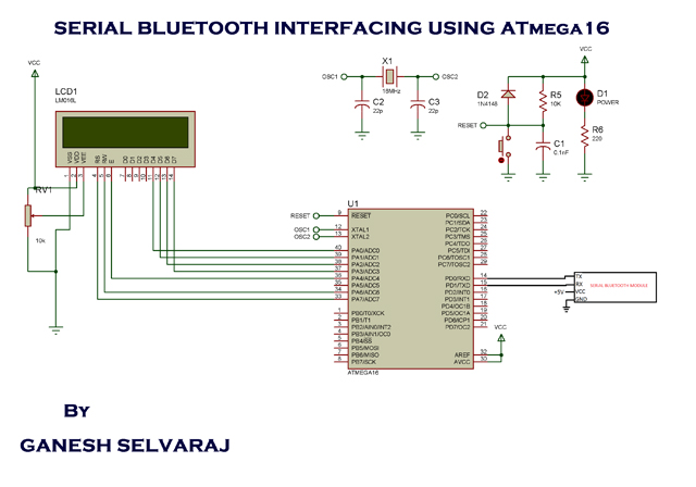
Circuit Diagrams
Project Video
Filed Under: Electronic Projects
Filed Under: Electronic Projects

Questions related to this article?
👉Ask and discuss on EDAboard.com and Electro-Tech-Online.com forums.
Tell Us What You Think!!
You must be logged in to post a comment.