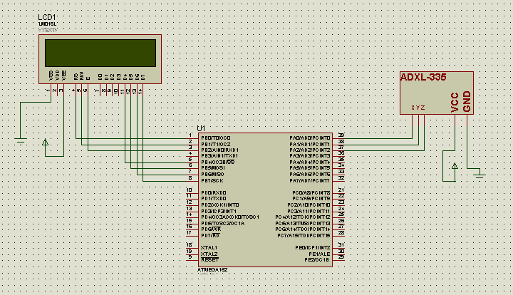
Engineers Garage

  • Electronic Projects & Tutorials
    • Electronic Projects
      • Arduino Projects
      • AVR
      • Raspberry pi
      • ESP8266
      • BeagleBone
      • 8051 Microcontroller
      • ARM
      • PIC Microcontroller
      • STM32
    • Tutorials
      • Audio Electronics
      • Battery Management
      • Brainwave
      • Electric Vehicles
      • EMI/EMC/RFI
      • Hardware Filters
      • IoT tutorials
      • Power Tutorials
      • Python
      • Sensors
      • USB
      • VHDL
    • Circuit Design
    • Project Videos
    • Components
  • Articles
    • Tech Articles
    • Insight
    • Invention Stories
    • How to
    • What Is
  • News
    • Electronic Product News
    • Business News
    • Company/Start-up News
    • DIY Reviews
    • Guest Post
  • Forums
    • EDABoard.com
    • Electro-Tech-Online
    • EG Forum Archive
  • DigiKey Store
    • Cables, Wires
    • Connectors, Interconnect
    • Discrete
    • Electromechanical
    • Embedded Computers
    • Enclosures, Hardware, Office
    • Integrated Circuits (ICs)
    • Isolators
    • LED/Optoelectronics
    • Passive
    • Power, Circuit Protection
    • Programmers
    • RF, Wireless
    • Semiconductors
    • Sensors, Transducers
    • Test Products
    • Tools
  • Learn
    • eBooks/Tech Tips
    • Design Guides
    • Learning Center
    • Tech Toolboxes
    • Webinars & Digital Events
  • Resources
    • Digital Issues
    • EE Training Days
    • LEAP Awards
    • Podcasts
    • Webinars / Digital Events
    • White Papers
    • Engineering Diversity & Inclusion
    • DesignFast
  • Guest Post Guidelines
  • Advertise
  • Subscribe

Interfacing triple-axis accelerometer with AtMega16

By Gurmeet Singh December 24, 2020

Requirements

  1. AtMega 16 IC /development board
  2. 2. 3-Axis accelerometer
  3. 3. LCD screen 16X2 (for displaying X, Y and Z data)

Description

This project makes use of three out of eight ADCs present in AtMega16 IC to display the corresponding digital data of X, Y and Z outputs of an accelerometer on 16X2  LCD.

Accelerometer

First let’s talk about the Accelerometer IC; here I have used ADXL-335 which is a 3-axis accelerometer module.

Image of ADXL335 Accelerometer Module

Fig. 1: Image of ADXL335 Accelerometer Module

It’s very easy to deal with such kinds of modules as they just need the VCC and GND supply to get started, the rest is its job to provide us the analog data. These modules work on a simple concept like that of force acting on an object at inclined plane. It deals with the Mg(sin ?) and Mg(cos ?) part of the force and determines the angle for further calculations. Now it also notices the change in force from which acceleration will be calculated.
These accelerometers do not respond to linear movements, they respond to accelerated motions at a very small scale.
Looking at the above picture you’ll notice that there is an ST pin which deals with the value of ‘g’ (accelerations due to gravity) to be taken while calculating the result. Check out its data sheet for more information. It will also work on a default value if you do not connect this pin anywhere.

Analog/Digital Converter

There are 8 independent ADCs which share their pins with that of PORTA. These ADCs are 10 bit which simply means that they can convert a given analog value into its corresponding 10-bit digital data.

Before moving ahead we should first discuss what ADCs are. ADC stands for Analog to Digital Converter. We all know that microcontrollers work only on digital values, but what if we need to interact with analog devices or values. In such situations we need a device which can work as communicator between the analog part and digital part. ADCs (analog to digital converter) play the same game; they convert the analog values to digital one by some means of reference (Vref).

In AtMega16, pin 32 requires a reference voltage (normally given +5V) when working with ADCs. Also there’s one more term that needs to be introduced i.e.Resolution. In simple terms we can say it’s the precision or accuracy with which an ADC works. For a 10 bit ADC working with 5V Vref, its resolution comes out to be 4.88mV. This further means for every rise or fall of 4.88mV in the analog input the digital output will increase or decrease by one unit, respectively. Since it’s a 10 bit ADC the output data will vary from 0- 1023(2^10=1024) having 1024 different values.
Now coming back to this project, I have connected the X, Y and Z pins to ADC0-ADC2. These provide individual and independent analog values. I have also displayed their corresponding digital outcome on the LCD.
The LCD connections are as follows:
• DATA pins are connected to PB4-PB7, since its working in 4-bit mode
• RS, RW and ES pins are connected to PB0, 1, 2 respectively.
While watching the video part you will notice  that, the X, Y and Z values vary in between 300-500 only. This is because my Vref is set at 5V while
the outputs from accelerometer remain between 1.6-1.9V.
In the coding part I have made use of three header files:
• <util/delay.h>                   for delay related functions
• <lcd.h>                            for LCD related functions
• <adc_lib.h>                     for ADC related functions


You may also like:


  • What are different types of industrial robots?

  • What are the components of robotic arms and industrial robots?

  • What are inertial sensors?

  • What is MicroPython?

  • What is sensor fusion?

  • Electronic Circuit Designing: Modular Approach (Part 1)

Project Source Code

###


#include

#include

#include

#include


void main()

{

      int adc0;

      ADCinit();

      LCDinit();

      LCDclr();

      LCDcursorOFF();

      char ch[16];


      while(1)

      {

                  adc0=read_adc(0);                   //reading X axis data

                  sprintf(ch,"X: %d",adc0);     //converting int to char

                  LCDGotoXY(0,0);

                  LCDdisplay(ch);

                  LCDsendChar(' ');


                  adc0=read_adc(1);                   //reading Y axis data

                  sprintf(ch,"Y: %d",adc0);

                  LCDGotoXY(0,10);

                  LCDdisplay(ch);

                  LCDsendChar(' ');


                  adc0=read_adc(2);                   //reading Z axis data

                  sprintf(ch,"Z: %d",adc0);

                  LCDGotoXY(1,5);

                  LCDdisplay(ch);

                  LCDsendChar(' ');


                  _delay_ms(500);                     //a half-second delay

}

}


###


Circuit Diagrams

Circuit-Diagram-ADXL335-Accelerometer-Module-Interfacing-AVR-ATMega16

Project Video


Filed Under: Electronic Projects
Tagged With: accelerometer, atmega16, avr
 

Next Article

← Previous Article
Next Article →

Questions related to this article?
👉Ask and discuss on Electro-Tech-Online.com and EDAboard.com forums.


Tell Us What You Think!! Cancel reply

You must be logged in to post a comment.

EE TECH TOOLBOX

“ee
Tech Toolbox: 5G Technology
This Tech Toolbox covers the basics of 5G technology plus a story about how engineers designed and built a prototype DSL router mostly from old cellphone parts. Download this first 5G/wired/wireless communications Tech Toolbox to learn more!

EE Learning Center

EE Learning Center
“engineers
EXPAND YOUR KNOWLEDGE AND STAY CONNECTED
Get the latest info on technologies, tools and strategies for EE professionals.

HAVE A QUESTION?

Have a technical question about an article or other engineering questions? Check out our engineering forums EDABoard.com and Electro-Tech-Online.com where you can get those questions asked and answered by your peers!


RSS EDABOARD.com Discussions

  • Exporting sensor readings as data...
  • Inconsistent Charge Termination Voltage with battery charger
  • 21V keeps getting shorted to my UART line.
  • Voltage mode pushpull is a nonsense SMPS?
  • Voltage mode push pull with extra DC blocking capacitor

RSS Electro-Tech-Online.com Discussions

  • Is AI making embedded software developers more productive?
  • Why can't I breadboard this oscillator?
  • using a RTC in SF basic
  • Parts required for a personal project
  • Cataract Lens Options?

Featured – RPi Python Programming (27 Part)

  • RPi Python Programming 21: The SIM900A AT commands
  • RPi Python Programming 22: Calls & SMS using a SIM900A GSM-GPRS modem
  • RPi Python Programming 23: Interfacing a NEO-6MV2 GPS module with Raspberry Pi
  • RPi Python Programming 24: I2C explained
  • RPi Python Programming 25 – Synchronous serial communication in Raspberry Pi using I2C protocol
  • RPi Python Programming 26 – Interfacing ADXL345 accelerometer sensor with Raspberry Pi

Recent Articles

  • GigaDevice launches GD32C231 MCU series with 48MHz Cortex-M23 core and 64KB Flash
  • Advanced Energy releases 425 W CF-rated medical power supply in 3.5 x 6 x 1.5-inch format”
  • LEM combines shunt and Hall effect sensing in 2000 A current measurement unit
  • What is AWS IoT Core and when should you use it?
  • AC-DC power supply extends voltage range to 800 V DC

EE ENGINEERING TRAINING DAYS

engineering

Submit a Guest Post

submit a guest post
Engineers Garage
  • Analog IC TIps
  • Connector Tips
  • Battery Power Tips
  • DesignFast
  • EDABoard Forums
  • EE World Online
  • Electro-Tech-Online Forums
  • EV Engineering
  • Microcontroller Tips
  • Power Electronic Tips
  • Sensor Tips
  • Test and Measurement Tips
  • 5G Technology World
  • Subscribe to our newsletter
  • About Us
  • Contact Us
  • Advertise

Copyright © 2025 WTWH Media LLC. All Rights Reserved. The material on this site may not be reproduced, distributed, transmitted, cached or otherwise used, except with the prior written permission of WTWH Media
Privacy Policy

Search Engineers Garage

  • Electronic Projects & Tutorials
    • Electronic Projects
      • Arduino Projects
      • AVR
      • Raspberry pi
      • ESP8266
      • BeagleBone
      • 8051 Microcontroller
      • ARM
      • PIC Microcontroller
      • STM32
    • Tutorials
      • Audio Electronics
      • Battery Management
      • Brainwave
      • Electric Vehicles
      • EMI/EMC/RFI
      • Hardware Filters
      • IoT tutorials
      • Power Tutorials
      • Python
      • Sensors
      • USB
      • VHDL
    • Circuit Design
    • Project Videos
    • Components
  • Articles
    • Tech Articles
    • Insight
    • Invention Stories
    • How to
    • What Is
  • News
    • Electronic Product News
    • Business News
    • Company/Start-up News
    • DIY Reviews
    • Guest Post
  • Forums
    • EDABoard.com
    • Electro-Tech-Online
    • EG Forum Archive
  • DigiKey Store
    • Cables, Wires
    • Connectors, Interconnect
    • Discrete
    • Electromechanical
    • Embedded Computers
    • Enclosures, Hardware, Office
    • Integrated Circuits (ICs)
    • Isolators
    • LED/Optoelectronics
    • Passive
    • Power, Circuit Protection
    • Programmers
    • RF, Wireless
    • Semiconductors
    • Sensors, Transducers
    • Test Products
    • Tools
  • Learn
    • eBooks/Tech Tips
    • Design Guides
    • Learning Center
    • Tech Toolboxes
    • Webinars & Digital Events
  • Resources
    • Digital Issues
    • EE Training Days
    • LEAP Awards
    • Podcasts
    • Webinars / Digital Events
    • White Papers
    • Engineering Diversity & Inclusion
    • DesignFast
  • Guest Post Guidelines
  • Advertise
  • Subscribe