Engineers Garage

  • Electronic Projects & Tutorials
    • Electronic Projects
      • Arduino Projects
      • AVR
      • Raspberry pi
      • ESP8266
      • BeagleBone
      • 8051 Microcontroller
      • ARM
      • PIC Microcontroller
      • STM32
    • Tutorials
      • Sensor Series
      • 3D Printing
      • AI
      • ARDUINO Compatible Coding
      • Audio Electronics
      • Battery Management
      • Beginners Electronics Series
      • Brainwave
      • Digital electronics (DE)
      • Electric Vehicles
      • EMI/EMC/RFI
      • EVs
      • Hardware Filters
      • IoT tutorials
      • LoRa/LoRaWAN
      • Power Tutorials
      • Protocol
      • Python
      • RPI Python Programming
      • Sensors
      • USB
      • Thermal management
      • Verilog
      • VHDL
    • Circuit Design
    • Project Videos
    • Components
  • Articles
    • Tech Articles
    • Insight
    • Invention Stories
    • How to
    • What Is
  • News
    • Electronic Product News
    • Business News
    • Company/Start-up News
    • DIY Reviews
    • Guest Post
  • Forums
    • EDABoard.com
    • Electro-Tech-Online
    • EG Forum Archive
  • DigiKey Store
    • Cables, Wires
    • Connectors, Interconnect
    • Discrete
    • Electromechanical
    • Embedded Computers
    • Enclosures, Hardware, Office
    • Integrated Circuits (ICs)
    • Isolators
    • LED/Optoelectronics
    • Passive
    • Power, Circuit Protection
    • Programmers
    • RF, Wireless
    • Semiconductors
    • Sensors, Transducers
    • Test Products
    • Tools
  • Learn
    • eBooks/Tech Tips
    • Design Guides
    • Learning Center
    • Tech Toolboxes
    • Webinars & Digital Events
  • Resources
    • Digital Issues
    • EE Training Days
    • LEAP Awards
    • Podcasts
    • Webinars / Digital Events
    • White Papers
    • Engineering Diversity & Inclusion
  • Guest Post Guidelines
  • Advertise
  • Subscribe

How to use internal timer registers of 8051(89c51,89c52) microcontroller

By EG Projects August 8, 2019

8051(89c51,89c52) series microcontrollers have two build in timers, Timer-0 and Timer-1. You can use them as counters, event counters. Since we can use them as counters so we can easily generate time-delays and baud rate for serial UART communication. They can also be used as interrupt counters. Both the 8051 microcontroller timers 0 and 1 are 16-bit wide. Since the timers are 16-bit wide the maximum range they can count is 2^16 (65535 times) after this value timers overflows. 

Timers actually counts the cycles that are generated by the crystal oscillator(clock) connected to pin 18(XTAL1) & 19(XTAL2) of 89c51 microcontroller. To understand the working of timer’s you should first know about the registers that are associated with timers.  

8051 Microcontroller Timer registers

To control the timer and specify our needs/logic we have to configure the timers first. For configuring and controlling the 89c51 microcontroller timers we have four registers. These registers are associated with timers of 89c51 microcontroller. Each register plays an important role in controlling and configuring the timer. 

  • (Timer Control register)
  • TMOD    (Timer Mode register)
  • TH0/TL0 (Timer 0, 16-bit register, High bits goes to TH0, Low bits goes to TL0)
  • TH1/TL1 (Timer 1, 16-bit register, High bits goes to TH1, Low bits goes to TL1)​

TH0/TL0(Timer-0) = TH1/TL1(Timer-1)

These two registers TH and TL are timer high byte and timer low byte registers. 0 and 1 are the timers numbers. These are 16-bit registers. we Load our time delays/counter value in these registers. Recall 8051 timer counter can count up to 65535 and 16 bits cover 65535 in binary.  Since 8051(89c51,89c52) is an 8-bit microcontroller, so to load 65535 we need two registers one representing the high byte and other the low byte. we access these register in two bytes one byte for TH(timer high byte) and TL(timer low byte). TH and TL together makes 16-bits(TH 8-bit, TL8-bit).  TH0 and TL0 are byte addressable only.

TCON(Timer control) Register of 8051 Microcontroller

TCON(Timer Control) is an 8-bit register. It’s bits are used for generating interrupts on gpio pins internal or external. The most important bits of the timers TRx and TFx are also in it. TRx(timer run) and TFx(timer overflow) bits which we use in almost all our timer applications are in it. When we initialize TRx with 1, TRx=1 it means start the timer, When the specified time is over the timer it self make TFx=1 which means that the delay value is reached. Once TFx=1 stop the timer by initializing TRx with 0 TRx=0(Stop Timer). Now if we again want to run the timer make TRx=1. In the diagram you can see the SFR for TCON register, the bit’s used for interrupt handling  and the timer run and timer over flow bits. If you want to access the individual bits of the registers, you can access them by their names. You can also access whole register it self by its name. At the bottom of the page their is a small example explaining it. 
89c51 microcontroller TCON register

89c51 microcontroller TCON register

 TCON (timer Control) register with its individual bits and sfr

TCON (timer Control) register with its individual bits and sfr

 88h is SFR(Special function registrar) address of TCON register

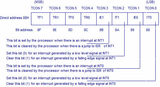
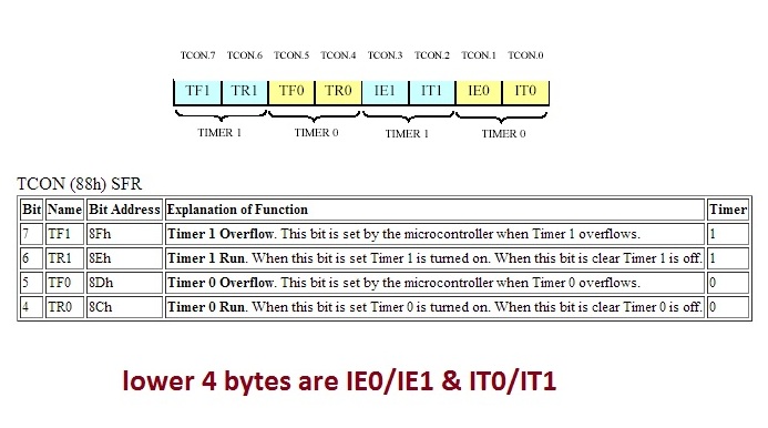
  • TR0/TR1: Timer 0/1 (Run control flag)
  • TF0/TF1: Timer 0/1 (Timer overflow flag)​

Lower Four bits are not shown in the above figure. These bits are

  •  IT0/IT1:  Timer Interrupts. when IT0=1 or IT1=1 It specifies interrupt on falling edge and when IT0=0 or IT1=0 it specifies interrupt on rising edge.
  • IE0/IE1: Used for external Interrupts.​

TMOD(Timer mode) Register of 8051 Microcontroller

TMOD is an eight bit register, it is bit addressable. Higher four bits (4 to 7) are related to Timer 1 where as the lower four bits (0 to 3) perform the exact same functions, but for timer 0. You can see their functions in the figure above.
TMOD (Timer Mode) register bits and sfr.

TMOD (Timer Mode) register bits and sfr.

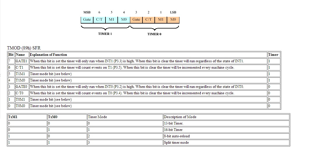
  •  T1M0-T1M1—-T0M1-T0M0: Selects the mode of the Timer. We can use timer as 13-bit counter or 16-bit counter by setting the above TMOD register bits. Other two modes are 8-bit auto reload and split timer mode. In auto reload mode once the counter reaches maximum value it automatically reloads or start from 1.    
  • C/T: Selects timer as external counter or Internal timer. If C/T is 1 timer as a counter is selected. External triggers on port#3 pin#4 are counted. If  C/T = 0 timer as a time delay generator is selected. It increments on every machine cycle and we can calculate our desired delay by multiplying the number of machine cycles with frequency of clock. 
  • Gate0-Gate1: When Gate is 1, Timer runs only when INT0-INT1 Pin of 89c51 is high.​ This bit represents timer interuupts and runs on a condition if interrupt-0 and interrupt-1 are high/occured.                                                          

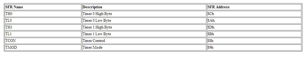
SFR’s(Special Function Registers) of 8051 Timer Registers

SFR are registers which contains address of different registers also the main or core functions of microprocessor architecture. We can access the registers directly or by their addresses. 89c51 microcontroller has some SFR’s registers. SFR’s registers names and addresses in memory are enlisted below.  
8051 microcontroller timers sfr's

8051 microcontroller Timers sfrs registers with names and addresses

89c51 Microcontroller register configuration examples

Note: we can access the registers by their names as well which make the programming easy and i am going to use them by their names and not by sfr addresses.
How to calculate values for TH and TL registers for generating needed delays?
Timer clock cycle duration for 89c51 microcontroller is given by
6 clock cycles represents one timer clock cycle =
Timer frequency=oscillator frequency/6
Timer frequency = 1 / Timer clock cycle duration

1 / Timer clock cycle duration = oscillator frequency/6

So by rearranging the variables, timer clock cycle comes out to be
Timer Clock Cycle Duration = 6/oscillator frequency 

Timer clock cycle duration is the time in which one cycle is completed by the timer. Divide the delay needed by the Timer clock cycle duration. For example I need a delay of 20 ms, Divide 20 ms by Timer Clock Cycle duration. Now negate the result of previous calculation from 65535, which is the maximum count by the timer with out over flow. Now transform the obtained decimal value in hexadecimal, and load the two high bytes in TH and low bytes in TL.

Divide the time reload value by 2 to achieve exact 20 ms delay value. It comes out to be 14336. Convert it in to Hexadecimal Format. Load the upper timer register with High byte and lower timer register with Low byte.   

Calculating Delay for 8051(89c51,89c52) microcontroller

Calculating timer reload values for delay generation 8051(89c51,89c52) microcontroller

                                  8051 Microcontroller Delay generation Steps

1.      Select Timer Mode in TMOD Register. Specify which Timer you want to use. Timer-1 or 0.
2.      Load values for TLx and THx registers.
3.      Run the timer by initializing TRx with 1 TR=1.
4.      Keep monitoring the timer flag (TFx). Tf it is raised Stop the timer by making TRx=0.
5.      Clear the TFx flag for the next count.

                                                      Simple Delay function
void Delay(void)
{
TMOD = 0x01;        // Timer 0 is in use. 16-bit Timer Mode is selected.  
TL0 = 0x00;           // Load value for TLx register
TH0 = 0x38;          // Load value for THx register
TR0 = 1;               // Run Timer-0
while(!TF0)         // Poll TFx  
TR0 = 0;             // If TF=1 stop the timer by making TR=0
TF0 = 0;             // Make TF=0 for next counting
}

                    Some Projects Created using same Delay method shown above

  • Digital Clock using 8051(89c51,89c52) Microcontroller.​
  • Generating One Second Delay using Timers of 8051(89c51,89c52) microcontroller.
  • Generating One Minute Delay using Timers of 8051(89c51,89c52) microcontroller.
Download PDF Document for 8051(89c51,89c52) Microcontroller Timers Registers

timers_of_805189c5189c52_microcontroller.pdf
File Size: 443 kb
File Type: pdf

Download File


Filed Under: Knowledge Share, Microcontroller Projects


Next Article

← Previous Article
Next Article →

Questions related to this article?
👉Ask and discuss on Electro-Tech-Online.com and EDAboard.com forums.


Tell Us What You Think!! Cancel reply

You must be logged in to post a comment.

Submit a Guest Post

submit a guest post

EE TECH TOOLBOX

“ee
Tech Toolbox: Power Efficiency
Discover proven strategies for power conversion, wide bandgap devices, and motor control — balancing performance, cost, and sustainability across industrial, automotive, and IoT systems.

EE Learning Center

EE Learning Center
“engineers
EXPAND YOUR KNOWLEDGE AND STAY CONNECTED
Get the latest info on technologies, tools and strategies for EE professionals.

HAVE A QUESTION?

Have a technical question about an article or other engineering questions? Check out our engineering forums EDABoard.com and Electro-Tech-Online.com where you can get those questions asked and answered by your peers!


RSS EDABOARD.com Discussions.

  • Cloning a HDD
  • Current sense transformer with Phase Shift Full Bridge
  • What is the frequency changing when I change the W?
  • PDKs setup for Virtuoso
  • Why do expensive synchronous rectifier controllers exist?

RSS Electro-Tech-Online.com Discussions

  • Manually actuate fuel tank selector solenoid
  • JLCPBC are using a different shipping company = less $$$$$$$$
  • Help please! BLDC driver circuit using the IR2136s and the STP80NF06 MOSFETS
  • need two ICs
  • MLT-8530 Buzzer on ESP32: Why Is the Sound Output Lower Than Expected?

Featured – Real Time Hardware Filter Design

  • Practical implementation of bandpass and band reject filters
  • Practical application of hardware filters with real-life examples
  • A filter design example
  • Types of filter responses
  • What are the two types of hardware filters?
  • What are hardware filters and their types?

Recent Articles

  • GigaDevices introduces 32-bit MCUs with integrated DSP and FPU support
  • Grinn introduces 8-core SBC supporting AI-ready embedded development
  • EPC’s 100 kHz BLDC inverter supports high-efficiency motion control
  • Melexis announces 5 W smart driver to supports sensorless FOC operation
  • STMicroelectronics’ motion sensor simplifies industrial IoT system design

EE ENGINEERING TRAINING DAYS

engineering
Engineers Garage
  • Analog IC TIps
  • Connector Tips
  • Battery Power Tips
  • EDABoard Forums
  • EE World Online
  • Electro-Tech-Online Forums
  • EV Engineering
  • Microcontroller Tips
  • Power Electronic Tips
  • Sensor Tips
  • Test and Measurement Tips
  • 5G Technology World
  • Subscribe to our newsletter
  • About Us
  • Contact Us
  • Advertise

Copyright © 2025 WTWH Media LLC. All Rights Reserved. The material on this site may not be reproduced, distributed, transmitted, cached or otherwise used, except with the prior written permission of WTWH Media
Privacy Policy

Search Engineers Garage

  • Electronic Projects & Tutorials
    • Electronic Projects
      • Arduino Projects
      • AVR
      • Raspberry pi
      • ESP8266
      • BeagleBone
      • 8051 Microcontroller
      • ARM
      • PIC Microcontroller
      • STM32
    • Tutorials
      • Sensor Series
      • 3D Printing
      • AI
      • ARDUINO Compatible Coding
      • Audio Electronics
      • Battery Management
      • Beginners Electronics Series
      • Brainwave
      • Digital electronics (DE)
      • Electric Vehicles
      • EMI/EMC/RFI
      • EVs
      • Hardware Filters
      • IoT tutorials
      • LoRa/LoRaWAN
      • Power Tutorials
      • Protocol
      • Python
      • RPI Python Programming
      • Sensors
      • USB
      • Thermal management
      • Verilog
      • VHDL
    • Circuit Design
    • Project Videos
    • Components
  • Articles
    • Tech Articles
    • Insight
    • Invention Stories
    • How to
    • What Is
  • News
    • Electronic Product News
    • Business News
    • Company/Start-up News
    • DIY Reviews
    • Guest Post
  • Forums
    • EDABoard.com
    • Electro-Tech-Online
    • EG Forum Archive
  • DigiKey Store
    • Cables, Wires
    • Connectors, Interconnect
    • Discrete
    • Electromechanical
    • Embedded Computers
    • Enclosures, Hardware, Office
    • Integrated Circuits (ICs)
    • Isolators
    • LED/Optoelectronics
    • Passive
    • Power, Circuit Protection
    • Programmers
    • RF, Wireless
    • Semiconductors
    • Sensors, Transducers
    • Test Products
    • Tools
  • Learn
    • eBooks/Tech Tips
    • Design Guides
    • Learning Center
    • Tech Toolboxes
    • Webinars & Digital Events
  • Resources
    • Digital Issues
    • EE Training Days
    • LEAP Awards
    • Podcasts
    • Webinars / Digital Events
    • White Papers
    • Engineering Diversity & Inclusion
  • Guest Post Guidelines
  • Advertise
  • Subscribe