Engineers Garage

  • Projects and Tutorials
    • Electronic Projects
      • 8051
      • Arduino
      • ARM
      • AVR
      • PIC
      • Raspberry pi
      • STM32
    • Tutorials
    • Circuit Design
    • Project Videos
    • Components
  • Articles
    • Tech Articles
    • Insight
    • Invention Stories
    • How to
    • What Is
  • News
    • Electronic Products News
    • DIY Reviews
    • Guest Post
  • Forums
    • EDABoard.com
    • Electro-Tech-Online
    • EG Forum Archive
  • Digi-Key Store
    • Cables, Wires
    • Connectors, Interconnect
    • Discrete
    • Electromechanical
    • Embedded Computers
    • Enclosures, Hardware, Office
    • Integrated Circuits (ICs)
    • Isolators
    • LED/Optoelectronics
    • Passive
    • Power, Circuit Protection
    • Programmers
    • RF, Wireless
    • Semiconductors
    • Sensors, Transducers
    • Test Products
    • Tools
  • EE Resources
    • DesignFast
    • LEAP Awards
    • Oscilloscope Product Finder
    • White Papers
    • Webinars
  • EE Learning Center
    • Design Guides
      • WiFi & the IOT Design Guide
      • Microcontrollers Design Guide
      • State of the Art Inductors Design Guide
  • Women in Engineering

Interrupts with NRF24LE1 (Part 3/14)

By Amanpreet Singh

Interrupts with NRF24LE1

In our daily life we get distracted or interrupted by others many times. In that condition we suspend our ongoing work and pay attention to what others have to say. We only resume our previously suspended work after the completion of the interrupted task. The master which controls the processing of thoughts in us is our brain. The brain stops processing ongoing thoughts when we get interrupted and starts processing the other task. It resumes the previous ongoing processing when the task is complete. The controller works in a similar manner. Here, we will study interrupts associated with our NRF.

Final Interrupt

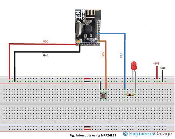
Fig. 1: Prototype of NRF24LE1 Interrupt Demonstration

We all know the task of interrupts in any controller. It tells the microcontroller to suspend its current execution of code, save the current state and process interrupt request. Controller processes interrupt request by jumping to Interrupt Service Routine (ISR) or Interrupt Handler. ISR is a function or procedure defined in the code which gets executed when interrupt occurs. Same is the case with NRF.

In NRF24LE1, there are total 18 sources for interrupts out of which 4 are hardware based and the rest are software based. Each Interrupt source has a vector address at which ISR has to be written. These interrupts can be level triggered (Low/High) or Edge triggered (Rise/Fall).
The attached image consists of different sources, vector address, polarity and their description.
In 32 pin package, there are 2 external hardware interrupts: INT0 and INT1. Interrupt pin for INT0 is P0.5 and for INT1 is P0.6.
Image of NRF24LE1 Interrupt Demonstration
Fig. 2: Image of NRF24LE1 Interrupt Demonstration
Interrupts can be controlled through various registers detailed below :
• Interrupt Enable 0 Register (IEN0) – An 8-bit register used to enable/disable global interrupts and Timer0, Timer1, Timer2, Port 0 and Serial Port individual interrupts.
• Interrupt Enable 1 Register (IEN1) – An 8-bit register used for enabling/disabling RF, SPI and Timer2 interrupts.
• INTEXP – This register enables/disables 2 wires, master and slave SPI interrupts. This register is also used to choose between INT0, INT1 and INT2.
• IP0 and IP1 (Interrupt Priority) – Two 8-bit registers used to set the priority levels among different sources.
• Interrupt Request Control Register (IRCON) – An 8-bit register this register contains interrupt request flags.
For software interrupt, we need to enable them according to functionalities we are using. For example, if we are using Timers then we will enable Timer interrupt which is associated with the internal timers of our module.
Image of NRF24LE1 Interrupt Demonstration
Fig. 2: Image of of NRF24LE1 Interrupt Demonstration
Presently we are focused on discussing hardware interrupts INT0. Some simple steps through which we can configure INT0 are-:
• First write 1 in bit7 of IEN0 to enable global interrupts and 1 in bit0.
• Write 1 in bit3 of INTEXP to select INT0.
• We have to write ISR for INT0
We have also written a code to explain the working of interrupt INT0. Besides, an LED blinking program has been written in our interrupt service routine. So the LED will blink whenever an interrupt occurs.
Check out the commented code for more details. Stay tuned for more articles in the series.


Project Source Code

###

//Program to 

#include"reg24le1.h" // I/O header file for NRF24LE1
#include // header file containing standard I/O functions
#include"hal_delay.h" // header file containing delay functions
#include"isrdef24le1.h" //header file containing Interrupt Service Routine definition for NRF24LE1
 
// main code
void main()
{
P0DIR = 0xf0; // make upper 4 bits of Port0 as input
P1DIR = 0;  // set Port1 as output
P1 = 0x00; // make all pins of Port1 low
IEN0 = 0x81; // enable interrupt from pin
INTEXP = 0x08; // enable INT0
while(1); // infinite loop, wait for interrupt
 
}
 
// Interrupt Service Routine
EXT_INT0_ISR()
{
P1 = 0xff; // make all pins of Port1 high
delay_ms(1000); // delay of 1 second
P1 = 0x00; // make all pins of Port1 Low
delay_ms(1000);  // delay of 1 second
}

###


Circuit Diagrams

Circuit-Diagram-NRF24LE1-Interrupt-Demonstration

Project Video


Filed Under: Tutorials


Questions related to this article?
👉Ask and discuss on Electro-Tech-Online.com and EDAboard.com forums.


Tell Us What You Think!! Cancel reply

You must be logged in to post a comment.

HAVE A QUESTION?

Have a technical question about an article or other engineering questions? Check out our engineering forums EDABoard.com and Electro-Tech-Online.com where you can get those questions asked and answered by your peers!


Featured Tutorials

  • PS2 Keyboard To Store Text In SD Card Using Arduino Circuit Setup On Breadboard
    How To Use PS2 Keyboard To Store Text In SD Card Using Arduino- (Part 42/49)
  • Wireless Path Tracking System Using Mouse, XBee And Arduino Circuit Setup On Breadboard
    How To Make A Wireless Path Tracking System Using Mouse, XBee And Arduino- (Part 43/49)
  • How to Make a Wireless Keyboard Using Xbee with Arduino- (Part 44/49)
  • Making Phone Call From GSM Module Using Arduino Circuit Setup On Breadboard
    How to Make Phonecall From GSM Module Using Arduino- (Part 45/49)
  • How to Make a Call using Keyboard, GSM Module and Arduino
    How To Make A Call Using Keyboard, GSM Module And Arduino- (Part 46/49)
  • Receiving SMS Using GSM Module With Arduino Prototype
    How to Receive SMS Using GSM Module with Arduino- (Part 47/49)

Stay Up To Date

Newsletter Signup

Sign up and receive our weekly newsletter for latest Tech articles, Electronics Projects, Tutorial series and other insightful tech content.

EE Training Center Classrooms

EE Classrooms

Recent Articles

  • Renesas delivers intelligent sensor solutions for IoT applications
  • Microchip Technology releases AVR-IoT Cellular Mini Development Board
  • Qualcomm acquires Cellwize to accelerate 5G adoption and spur infrastructure innovation
  • MediaTek’s chipset offers high-performance option for 5G smartphones
  • Nexperia’s new level translators support legacy and future mobile SIM cards

Most Popular

5G 555 timer circuit 8051 ai Arduino atmega16 automotive avr bluetooth dc motor display Electronic Part Electronic Parts Fujitsu ic infineontechnologies integratedcircuit Intel IoT ir lcd led maximintegratedproducts microchip microchiptechnology Microchip Technology microcontroller microcontrollers mosfet motor powermanagement Raspberry Pi remote renesaselectronics renesaselectronicscorporation Research samsung semiconductor sensor software STMicroelectronics switch Technology vishayintertechnology wireless

RSS EDABOARD.com Discussions

  • Using LTspice to check Current sense transformer reset?
  • Plotting E_theta and E_phi using the fields calculator in HFSS
  • SRF04 module measure distance
  • Motherboard - worst case scenario
  • Will Wifi throughput be affected by RSSI (attenuation) in my setup?

RSS Electro-Tech-Online.com Discussions

  • Are Cross-wind compensation and Road crown compensation functions inputs to LKA function?
  • Interfacing ZMOD4410 with Arduino UNO
  • Help diagnosing a coffee maker PCB
  • Capacitor to eliminate speaker hum
  • Identify a circuit.
Engineers Garage
  • Analog IC TIps
  • Connector Tips
  • DesignFast
  • EDABoard Forums
  • EE World Online
  • Electro-Tech-Online Forums
  • Microcontroller Tips
  • Power Electronic Tips
  • Sensor Tips
  • Test and Measurement Tips
  • 5G Technology World
  • About Us
  • Contact Us
  • Advertise

Copyright © 2022 WTWH Media LLC. All Rights Reserved. The material on this site may not be reproduced, distributed, transmitted, cached or otherwise used, except with the prior written permission of WTWH Media
Privacy Policy | Advertising | About Us

Search Engineers Garage

  • Projects and Tutorials
    • Electronic Projects
      • 8051
      • Arduino
      • ARM
      • AVR
      • PIC
      • Raspberry pi
      • STM32
    • Tutorials
    • Circuit Design
    • Project Videos
    • Components
  • Articles
    • Tech Articles
    • Insight
    • Invention Stories
    • How to
    • What Is
  • News
    • Electronic Products News
    • DIY Reviews
    • Guest Post
  • Forums
    • EDABoard.com
    • Electro-Tech-Online
    • EG Forum Archive
  • Digi-Key Store
    • Cables, Wires
    • Connectors, Interconnect
    • Discrete
    • Electromechanical
    • Embedded Computers
    • Enclosures, Hardware, Office
    • Integrated Circuits (ICs)
    • Isolators
    • LED/Optoelectronics
    • Passive
    • Power, Circuit Protection
    • Programmers
    • RF, Wireless
    • Semiconductors
    • Sensors, Transducers
    • Test Products
    • Tools
  • EE Resources
    • DesignFast
    • LEAP Awards
    • Oscilloscope Product Finder
    • White Papers
    • Webinars
  • EE Learning Center
    • Design Guides
      • WiFi & the IOT Design Guide
      • Microcontrollers Design Guide
      • State of the Art Inductors Design Guide
  • Women in Engineering