Engineers Garage

  • Electronic Projects & Tutorials
    • Electronic Projects
      • Arduino Projects
      • AVR
      • Raspberry pi
      • ESP8266
      • BeagleBone
      • 8051 Microcontroller
      • ARM
      • PIC Microcontroller
      • STM32
    • Tutorials
      • Audio Electronics
      • Battery Management
      • Brainwave
      • Electric Vehicles
      • EMI/EMC/RFI
      • Hardware Filters
      • IoT tutorials
      • Power Tutorials
      • Python
      • Sensors
      • USB
      • VHDL
    • Circuit Design
    • Project Videos
    • Components
  • Articles
    • Tech Articles
    • Insight
    • Invention Stories
    • How to
    • What Is
  • News
    • Electronic Product News
    • Business News
    • Company/Start-up News
    • DIY Reviews
    • Guest Post
  • Forums
    • EDABoard.com
    • Electro-Tech-Online
    • EG Forum Archive
  • DigiKey Store
    • Cables, Wires
    • Connectors, Interconnect
    • Discrete
    • Electromechanical
    • Embedded Computers
    • Enclosures, Hardware, Office
    • Integrated Circuits (ICs)
    • Isolators
    • LED/Optoelectronics
    • Passive
    • Power, Circuit Protection
    • Programmers
    • RF, Wireless
    • Semiconductors
    • Sensors, Transducers
    • Test Products
    • Tools
  • Learn
    • eBooks/Tech Tips
    • Design Guides
    • Learning Center
    • Tech Toolboxes
    • Webinars & Digital Events
  • Resources
    • Digital Issues
    • EE Training Days
    • LEAP Awards
    • Podcasts
    • Webinars / Digital Events
    • White Papers
    • Engineering Diversity & Inclusion
    • DesignFast
  • Guest Post Guidelines
  • Advertise
  • Subscribe

Introduction to Logic Gates

By Arpit jain April 21, 2008

You must have heard that calculators and computers store decimal numbers in the form of binary code as long strings of Zeroes and Ones.  In internal circuitry, each digit (0 or 1) is stored in electronic switches called transistors. It is easy to store binary numbers simply by switching the transistor On and Off. We can say that switching ON the transistor represents number 1 and switching OFF represents number 0.  But how can we add, multiply, subtract or perform various mathematical operations using just electrical currents? This can be done by using smart and logical circuits known as Logic Gates.

What are Logic Gates?

The word “logic” itself gives us an idea that they work on certain kind of logical operations. A gate can keep us restricted or can allow us to go out. In a similar manner, logic gate can either restrict electricity or let it flow.  As from childhood, we have learnt about logical operations in mathematics such as +, *, –, etc. Similarly, we can relate mathematical logical operations with the operations of logic gates.

Logic gates are the basic building blocks of digital electronics which have 1 or more input signals based on which it gives one logical output. Logic gate works on digital signals only and there are two states of these signals i.e. 0 as low and 1 as high or ON and OFF state. That’s why Logic Gates are known as digital electronic devices. The logical state of any terminal of gate can change its state, and it does generally change, as processing is happening in the circuit.  A table which gives the relation between different input signals corresponding to its output is known as Truth Table. By the help of this truth table we can identify how logic circuit works in response with different input signals which we apply to logic gates. An example of truth table of AND gate can be seen below where output is “1” only when both the inputs are “1” else the output is 0.


INPUT INPUT OUTPUT
A B Y
0 0 0
0 1 0
1 0 0
1 1 1


There are two types of logic state, namely positive logic and negative logic. Positive logic is generally used by most of the electronics devices, whereby we consider higher voltage levels as 1 and lower voltage levels as 0. For example, in logic gates we consider +5V as 1 and from range 0V to 0.49V as 0. Whereas in negative logic we take high voltage levels as 0 and low voltage levels as 1.

Based on the input-output relation we have different kinds of logic gates. Three basic logic gates are as follows OR gate, AND gate and NOT gate. Others are NAND, NOR, XOR and ExOR gates.
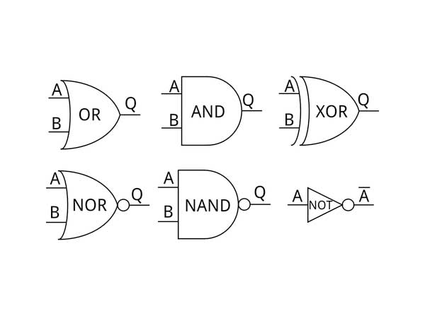
Symbols of Logic Gates

By using different combinations of Logic gates, many advanced and complex circuits can be achieved. Theoretically, there is no limit on the number of gates to be arrayed in a single circuit but practically, only limited number of gates can be arranged in a given physical space. Different ICs contain arrangements of different logic gates. Also, as logical gates are mathematical symbols, it is possible to do any sort of calculation by the arrangement of different logic gates.

Let us know about your thoughts, doubts or feedback in the comments section below.


Filed Under: Electronic Projects


Next Article

← Previous Article
Next Article →

Questions related to this article?
👉Ask and discuss on EDAboard.com and Electro-Tech-Online.com forums.


Tell Us What You Think!! Cancel reply

You must be logged in to post a comment.

EE TECH TOOLBOX

“ee
Tech Toolbox: 5G Technology
This Tech Toolbox covers the basics of 5G technology plus a story about how engineers designed and built a prototype DSL router mostly from old cellphone parts. Download this first 5G/wired/wireless communications Tech Toolbox to learn more!

EE Learning Center

EE Learning Center
“engineers
EXPAND YOUR KNOWLEDGE AND STAY CONNECTED
Get the latest info on technologies, tools and strategies for EE professionals.

HAVE A QUESTION?

Have a technical question about an article or other engineering questions? Check out our engineering forums EDABoard.com and Electro-Tech-Online.com where you can get those questions asked and answered by your peers!


RSS EDABOARD.com Discussions

  • Inconsistent Charge Termination Voltage with battery charger
  • 21V keeps getting shorted to my UART line.
  • Voltage mode pushpull is a nonsense SMPS?
  • Voltage mode push pull with extra DC blocking capacitor
  • NXP library issue in awr

RSS Electro-Tech-Online.com Discussions

  • Is AI making embedded software developers more productive?
  • Why can't I breadboard this oscillator?
  • using a RTC in SF basic
  • Parts required for a personal project
  • Cataract Lens Options?

Featured – RPi Python Programming (27 Part)

  • RPi Python Programming 21: The SIM900A AT commands
  • RPi Python Programming 22: Calls & SMS using a SIM900A GSM-GPRS modem
  • RPi Python Programming 23: Interfacing a NEO-6MV2 GPS module with Raspberry Pi
  • RPi Python Programming 24: I2C explained
  • RPi Python Programming 25 – Synchronous serial communication in Raspberry Pi using I2C protocol
  • RPi Python Programming 26 – Interfacing ADXL345 accelerometer sensor with Raspberry Pi

Recent Articles

  • GigaDevice launches GD32C231 MCU series with 48MHz Cortex-M23 core and 64KB Flash
  • Advanced Energy releases 425 W CF-rated medical power supply in 3.5 x 6 x 1.5-inch format”
  • LEM combines shunt and Hall effect sensing in 2000 A current measurement unit
  • What is AWS IoT Core and when should you use it?
  • AC-DC power supply extends voltage range to 800 V DC

EE ENGINEERING TRAINING DAYS

engineering

Submit a Guest Post

submit a guest post
Engineers Garage
  • Analog IC TIps
  • Connector Tips
  • Battery Power Tips
  • DesignFast
  • EDABoard Forums
  • EE World Online
  • Electro-Tech-Online Forums
  • EV Engineering
  • Microcontroller Tips
  • Power Electronic Tips
  • Sensor Tips
  • Test and Measurement Tips
  • 5G Technology World
  • Subscribe to our newsletter
  • About Us
  • Contact Us
  • Advertise

Copyright © 2025 WTWH Media LLC. All Rights Reserved. The material on this site may not be reproduced, distributed, transmitted, cached or otherwise used, except with the prior written permission of WTWH Media
Privacy Policy

Search Engineers Garage

  • Electronic Projects & Tutorials
    • Electronic Projects
      • Arduino Projects
      • AVR
      • Raspberry pi
      • ESP8266
      • BeagleBone
      • 8051 Microcontroller
      • ARM
      • PIC Microcontroller
      • STM32
    • Tutorials
      • Audio Electronics
      • Battery Management
      • Brainwave
      • Electric Vehicles
      • EMI/EMC/RFI
      • Hardware Filters
      • IoT tutorials
      • Power Tutorials
      • Python
      • Sensors
      • USB
      • VHDL
    • Circuit Design
    • Project Videos
    • Components
  • Articles
    • Tech Articles
    • Insight
    • Invention Stories
    • How to
    • What Is
  • News
    • Electronic Product News
    • Business News
    • Company/Start-up News
    • DIY Reviews
    • Guest Post
  • Forums
    • EDABoard.com
    • Electro-Tech-Online
    • EG Forum Archive
  • DigiKey Store
    • Cables, Wires
    • Connectors, Interconnect
    • Discrete
    • Electromechanical
    • Embedded Computers
    • Enclosures, Hardware, Office
    • Integrated Circuits (ICs)
    • Isolators
    • LED/Optoelectronics
    • Passive
    • Power, Circuit Protection
    • Programmers
    • RF, Wireless
    • Semiconductors
    • Sensors, Transducers
    • Test Products
    • Tools
  • Learn
    • eBooks/Tech Tips
    • Design Guides
    • Learning Center
    • Tech Toolboxes
    • Webinars & Digital Events
  • Resources
    • Digital Issues
    • EE Training Days
    • LEAP Awards
    • Podcasts
    • Webinars / Digital Events
    • White Papers
    • Engineering Diversity & Inclusion
    • DesignFast
  • Guest Post Guidelines
  • Advertise
  • Subscribe