In the previous tutorial, communication between two PCs was setup over Zigbee Protocol using Xbee modules and XCTU software. In this tutorial, two Xbee module based IoT devices will be designed and configured to communicate with each other over Zigbee protocol. One of these devices in the Zigbee network will be a Coordinator device and the other will be a Router device. The coordinator device will control LED interfaced at the Router device.
The Zigbee Protocol is one of the most popular standard for Wireless Sensor Networks. The Zigbee is commonly used in industrial IoT applications.
The Xbee devices communicate with each other wirelessly over the air. They do not have any microcontroller or processor in themselves, so they cannot manage the received or sent data. They can simply transfer the information what they receive. But they can be interfaced with other microcontrollers and processors like Arduino, Raspberry Pi or PC via serial Interface.
So, basically, Xbee modules are capable of two types of communication – wireless communication and serial communication. The wireless communication takes place between Xbee devices so that the devices act as radio frequency (RF) devices. For data to transmit and receive from one Xbee module to another, both devices should be on same network. The data between two devices is transmitted wirelessly. By serial communication (UART), the Xbee modules can communicate with microcontrollers and processors.
A microcontroller, processor or PC can send data through the serial interface to the Xbee module (transmitter) and the Xbee module wirelessly transmits the data to other Xbee module (Receiver). The receiver Xbee module transmits the data through the serial interface to controller, processor or PC to which it is interfaced. The controller interfaced to the Xbee module processes the information received by the Xbee devices. This way, controllers can monitor and control remote devices by sending messages through the local Xbee modules.
The Xbee modules communicate with each other in two modes – Transparent mode and API (Application Peripheral Interface) mode. This project is based on Transparent mode. In transparent mode, Xbee modules act as serial line replacement. All data received through serial input is immediately transmitted over the air. When other Xbee module receives data wirelessly, it sends that exactly as it receives through the serial interface and vice versa. Contrary to this, in the API mode, the data is transmitted with some additional information.
In this project, two Xbee modules will be interfaced with Arduino boards. They will be configured to communicate data with each other in transparent mode. One of the Arduino device will be interfaced with an LED and will be configured as Zigbee Router. The other Arduino device will be configured as Zigbee Coordinator. The Coordinator device will control LED interfaced at Router device by passing messages over Zigbee protocol. The Xbee modules interfaced in both devices will be configured as coordinator or router using XCTU software.
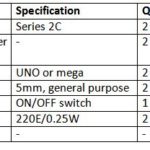
Component Required –

Fig. 1: List of components required for Zigbee based Device to Device IoT Communication
Software Required –
• XCTU (6.3.1 or later) or XCTU legacy
• Arduino IDE
Block Diagram –

Fig. 2: Block Diagram of Zigbee bassed Device to Device IoT Communication
Circuit Connections –
The Xbee Series 2 modules will be used in this project. The X-Bee module is a 20-pin module with the following pin configuration –


Fig. 3: Table listing pin configuration of Xbee Series 2 Module
For connecting the module with PC for configuration, first place the Xbee to the Xbee Shield and connect module with an Arduino. The Arduino UNO or Arduino Mega acts as a USB converter for Xbee modules. Before using Arduino UNO with Xbee modules, a bare minimum sketch must be uploaded on it or the Atmega microcontroller must be removed from the board. The Xbee module can be provided power by an external power supply or from the Arduino. The Xbee module and the Arduino board must communicate serially. The Xbee module should be connected to the Arduino according to the following table –

Fig. 4: Table listing circuit connections between Arduino and Xbee Series 2 Module
Now Arduino can be connected with the PC using a USB cable.
After connecting the module to the computer, perform the following steps –
1) Open the XCTU software. Make sure, the software is in configuration working mode.
2) Click on “Discover Radio Modules”.
3) Click on the desired COM port on which module is connected.
4) Click next, in the ‘Set port parameters’ window, change the values according to the requirements and click finish.
5) As XCTU locates radio modules after full scan, select the radio modules by clicking on ‘Add selected devices’. Now, the selected radio modules should show in radio module window.
In order to transmit or receive data on Xbee modules, they need to be properly configured on the same network. According to the Zigbee protocol one device needs to be in coordinator mode and the rest can be router or end devices. In this case, one device is coordinator and other is router.
Now, restore the default setting of all Xbee modules with the ‘Load default firmware setting’ button at the top of Radio configuration section and use XCTU to configure the following parameter –

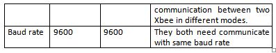
Fig. 5: Table listing configuration parameters of Xbee Module
Keep the rest of the values as default and write the settings of all Xbee modules with the ‘write radio modules’ button at the top of radio configuration. Once the configuration is completed, click on the discover radio modules on same network button of any of the radio module. Now, the radio modules for the same network can be found.
Now the Xbee modules can be connected in the Arduino based IoT devices.
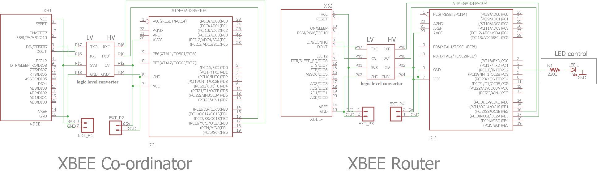
One of these devices will operate as Zigbee Coordinator. Connect the Xbee module configured as coordinator in its circuit. The Xbee module can communicate with Arduino through serial communication. The Arduino software serial is used to read the data from Xbee and hardware serial to read the controller serial data. As Xbee operates on CMOS logic level and Arduino operates on TTL logic level, there is need of a logic level converter. A 5V to 3.3V IIC I2C Logic Level Interface Level Converter Module for Arduino is used as logic level converter. The Xbee module can be provided power by an external source or from the Arduino. For serial communication between the Arduino board and the Xbee module, RX pin of Xbee is connected to TX of Arduino and TX pin of Xbee is connected to RX of Arduino. The ground pin is connected to the common ground.
The other device act as Zigbee Router. Connect the Xbee module configured as router in its circuit. The Xbee module is connected to the Arduino in the similar manner. An LED is interfaced with the Arduino at its PD2 (pin 4) pin through a pull up resistor of 220 ohms.
The following precautions must be taken care while interfacing the Xbee modules –
1) Xbee modules operate on 3V3 with current of 40 mA to transmit and receive the data. Don’t provide 5V from Arduino.
2) Xbee modules have 3V3 tolerant signal level. For providing communication between arduino and Xbee, use CMOS-to-TTL logic level converter (Bidirectional).
3) Sometimes when trying to discover Xbee, there may occur an error like – ‘Could not find any device in port COM6 >For input string: “ERROR” or error initializing device parameter = connection timeout or could not find device parameter’ then the error may be because of the incorrect baud rate.
For this, connect the modem using FTDI cable to the PC, open XCTU, select the COM port and multiple baud rates like 9600, 115200, 57600 then search for the radio module and possibly there the radio module can be found. But if not found, then open XCTU legacy (old version), select the possible baud rate and in the modem configuration window select the correct modem firmware/ function set, then enable ‘always update firmware’ and select write. After that, when the info box (action required) appears, then reset the Xbee by connecting RST to GND or simply unseat the Xbee and again place on seat. Now info box will disappear. It will then re-flash the radio modules automatically.
4) If there comes the error of baud rate difference then the error can be that the PC and radio module are not working on same baud rate. In such case, try to change the PC and flash the firmware with another PC. The Xbee module can also be recovered this way.
5) Issue the commands properly when working in AT mode.

Fig. 6: Prototype of Xbee and Arduino based Zigbee Coordinator and Router
How the circuit works –
The coordinator Xbee controls the LED of router Xbee. The Xbee modules are interfaced with the Arduino boards which are programmed to communicate specific messages. First, the coordinator bee continuously listens for any serial message. The Arduino board on Coordinator Xbee issues the commands 0 or 1 through the serial monitor to the coordinator Xbee. The router Xbee continuously listens for any wireless radio message. The coordinator Xbee passes the same information (0 or 1) to the router Xbee in wireless mode. Now, the router Xbee serially passes the same information with no additional data to the Arduino board interfaced to it.
The Arduino serial check whether the information received in is 0 or 1. If it is 1, it implies that LED connected to the board should set to glow by setting the LED connected pin HIGH. If it is 0 then it implies that LED connected to the board should stop glowing by setting the LED connected pin LOW.
The following code on the receiver Arduino controls LED according to the message received over Zigbee protocol.
if(xbee_s2c.available()>0) //has Xbee received something?
{
input = Serial.write(xbee_s2c.read()); //send it to Arduino serial
if (input == ‘0’)
{digitalWrite(2, HIGH);}
if (input == ‘1’)
{digitalWrite(2, LOW); }
}
Check out the Arduino sketches to learn how they communicate with the Xbee modules using software serial, transmit and receive specific messages (hard coded in firmware) and control LED on communicating specific messages between each other. This is a simple demonstration of IoT communication between two devices over Zigbee protocol.
In the next tutorial, learn to design an LED Light Controller Over Zigbee using Xbee Modules.
You may also like:


Project Source Code
### //Program to /* @Application: Arduino_sends_data_to_xbee @Hardware used: Arduino UNO Xbee sereies 2 module External Power supply @Connection: Xbee VCC- External power supply 3v3 Xbee GND- EXternal power supply GND Xbee TX- Arduino digital pin 11 Xbee RX- Arduino digital pin 10 External power supply GND - Arduino GND @Brief Introduction: Transmitter side: The arduino serial sends the data to Xbee serial. And if xbee receives some data wirelessly from other xbee then it sends to arduino serial For more detail, Refer our Article! */ //include software serial to communicate with Xbee #include//Create an instance for software serial SoftwareSerial xbee(10,11); //Digital pin 10- Xbee RX, Digital pin 11- Xbee TX void setup() { // Initialize serial communicate, //we configured our XBEE devices for 9600 bps. Serial.begin(9600); xbee.begin(9600); } void loop() { //Check whether serial has something to send or not if(Serial.available()>0) { //If serial has data to write, then pass that data to Xbee xbee.write(Serial.read()); } //Check whether Xbee received something or not on software serial port. else if (xbee.available()>0) { //If it received something, pass it to Arduino serial Serial.write(xbee.read()); } } ###
Circuit Diagrams
Project Video
Filed Under: Featured Contributions, IoT, IoT tutorials, Tutorials
Filed Under: Featured Contributions, IoT, IoT tutorials, Tutorials

Questions related to this article?
👉Ask and discuss on EDAboard.com and Electro-Tech-Online.com forums.
Tell Us What You Think!!
You must be logged in to post a comment.