Arduino can be used to vary different colors in RGB bulb (LED). We know Arduino can vary the intensity of LED using its analog outputs by generating PWM. The RGB bulb has 3 internal LEDs – red, green and blue. The Arduino varies the intensity of all three red, green and blue LED and thus it gives different mixtures of these three colors and generates different colors like CYAN, PINK, YELLOW, MAGENTA, WHITE etc. By varying the intensity of all three LEDs from minimum to maximum we can have many numbers of color combinations- means different colors. So Arduino can generate many different colors using RGB bulb.
What if we can turn ON or OFF RGB bulb or vary its different colors using IR remote? Especially normal, readily available, handheld IR remote which we can find in all most all the homes for TV, AC, music systems, DVD or even for STB (set top box). Means we can turn ON the bulb or turn OFF the bulb or set any color of bulb using such IR remote – any IR remote. Sounds interesting?
The given project demonstrates how to turn ON/OFF or vary colors of RGB bulb using any IR remote (like TV, DVD, AC, STB etc) with the help of Arduino. The project uses a normal set top box (STB) IR remote, TSOP IR sensor and Arduino UNO board. Anyone can use any type of IR remote. Just he has to change the remote codes in the Arduino sketch (program) for the remote. This procedure is also described here while explaining the operation. So let us see how this is done. First, see the circuit diagram followed by its description and operation.
CIRCUIT DESCRIPTION
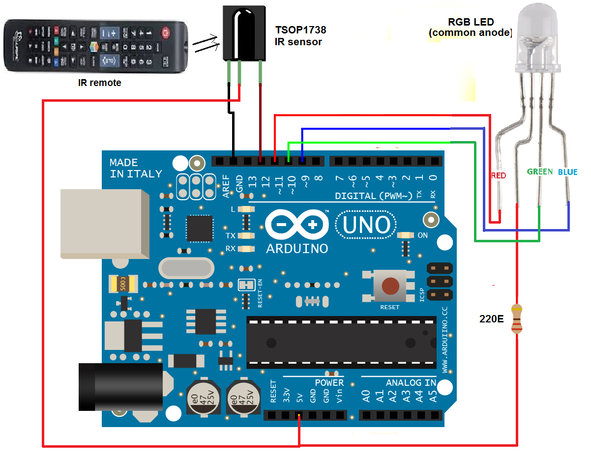
As shown in the figure, the circuit is built using 3 components only an Arduino board, IR sensor and RGB LED.
• The sensor TSOP1738 has 3 terminals (1) Vcc (2) Gnd and (3) output. Its Vcc terminal is given 5 V from board and Gnd terminal is connected to the ground of board. The sensor output is connected digital input pin 12 of arduino board.
• The RGB LED is common anode type. Its common anode is given 5 V supply from the board through the current limiting resistor and red, green and blue LED terminals are connected to analog output pins 9, 10 and 11 respectively.
Here is the snap of circuit arrangement.

Fig. 1: Prototype of Arduino and IR Remte based RGB Bulb Controller
CIRCUIT OPERATION
First, we have to decide, which are the different buttons of IR remote that we will be used to vary colors of RGB ball. We want to perform following actions -:
1. ON/OFF RGB bulb
2. Increase / decrease red colour intensity
3. Increase / decrease green colour intensity
4. Increase / decrease blue colour intensity
So we require 7 buttons. I have used set-top box (STB) remote that has many buttons like 0-9 digit buttons, volume control buttons, channel up/down buttons, arrow key buttons etc. From all these buttons I have selected following 7 buttons for different operations -:

Fig. 2: Table listing IR Remote buttons and respective functions in RGB Bulb Control
After deciding the buttons next is to decode the codes of these buttons. As we know when any button is pressed from remote, it will send one code and based on this code the action is performed. So to decode these codes I have used IRremote functions and IRremote library for arduino, readily available on the internet.
So download the library and use an example to decode the codes of remote buttons. Upload the program into arduino microcontroller and connect IR sensor as shown in the figure. Now point the remote control towards IR sensor and press the button. Open serial monitor and you can observe the code of pressed button in form of numbers. Note down the codes of required buttons like I have noted the codes as per the following table -:

Fig. 3: Table listing IR Remote buttons and respective IR Codes
In the arduino sketch above codes are used corresponding to button pressed to perform an action as per the previous table. Now let us see the actual operation.
• When the power button is pressed from remote, it will turn ON RGB bulb. Pressing the same button once again will turn OFF the RGB bulb. Thus power button of remote is used to turn ON / OFF RGB bulb. The message is also displayed on serial monitor as “RGB bulb ON” and “RGB bulb OFF”
• The volume up button is used to increase the intensity of red color (RED LED) and volume down button will decrease the intensity of RED LED. RED LED intensity is increased from 1% to full 100%. As the buttons are pressed it will increase or decrease the pulse width on analog output pin 11 from 1 to 100% to change the intensity of red LED. The message is displayed on a serial monitor as “red intensity is increased by XX%” or “red intensity is decreased by XX%”.
• Similarly to change blue color intensity two other buttons CH+ and CH- are used. CH+ button will increase blue color intensity and CH- will decrease it. These two buttons will increase or decrease the pulse width on analog output pin 9 and thus they will vary blue LED intensity from 1 to 100%.
• Finally to vary green LED intensity up arrow and down arrow buttons are used. Up arrow button will increase the intensity and down arrow key will decrease the intensity. These two buttons will increase or decrease pulse width on analog output pin 10 and will vary green LED intensity from 1 to 100%.
• Thus by changing/varying/setting different color intensity using all these six buttons, we may get different colors of RGB bulb.
Project Source Code
###
#includeint IRpin = 12; // pin for the IR sensor int red = 9; int green = 10; int blue = 11; /////////////////// initial values of colour intensity///////////////////// int red_intensity=130,i; int blue_intensity=130; int green_intensity=130; IRrecv irrecv(IRpin); decode_results results; void setup() { Serial.begin(9600); // initialize serial communication Serial.println("Remote control RGB Light"); irrecv.enableIRIn(); // Start the receiver } void loop() { // loop until no button is pressed no code is received while(!(irrecv.decode(&results))); if (irrecv.decode(&results)) // when code is received { // start comparing results if(results.value==6296) // for power on button { analogWrite(red,red_intensity); // turn ON bulb with analogWrite(green,green_intensity); // default colour analogWrite(blue,blue_intensity); Serial.println("RGB Bulb ON"); // display message } else if(results.value==2200) // for even times { analogWrite(red,255); // turn OFF bulb analogWrite(green,255); analogWrite(blue,255); Serial.println("RGB Bulb OFF"); } else if(results.value==6338) // for volume UP button { // decrease pulse width means increase colour intensity if(red_intensity>5) red_intensity-=25; Serial.print("red intensity increased to "); i = 100-red_intensity*100/255; // convert it into 1 to 100% Serial.println(i); // display it on serial monitor analogWrite(red,red_intensity); } else if(results.value==6292) // for volume down button { // increase pulse width means decrease colour intensity if(red_intensity<255) red_intensity+=25; Serial.print("red intensity decreased to "); i= 100-red_intensity*100/255; // convert it into 1 to 100% Serial.println(i); // display it on serial monitor analogWrite(red,red_intensity); } else if(results.value==2205) // same as above for green colour LED { if(green_intensity>5) green_intensity-=25; Serial.print("green intensity increased to "); i=100 - green_intensity*100/255; Serial.println(i); analogWrite(green,green_intensity); } else if(results.value==2199) { if(green_intensity<255) green_intensity+=25; Serial.print("green intensity decreased to "); i=100 - green_intensity*100/255; Serial.println(i); analogWrite(green,green_intensity); } else if(results.value==6377) //same as above for blue colour LED { if(blue_intensity>5) blue_intensity-=25; Serial.print("blue intensity increased to "); i=100 - blue_intensity*100/255; Serial.println(i); analogWrite(blue,blue_intensity); } else if(results.value==6378) { if(blue_intensity<255) blue_intensity+=25; Serial.print("blue intensity decreased to "); i=100 - blue_intensity*100/255; Serial.println(i); analogWrite(blue,blue_intensity); } delay(200); // wait for 200 ms irrecv.resume(); // Receive the next value } } ###
Circuit Diagrams
Project Video
Filed Under: Electronic Projects
Filed Under: Electronic Projects

Questions related to this article?
👉Ask and discuss on EDAboard.com and Electro-Tech-Online.com forums.
Tell Us What You Think!!
You must be logged in to post a comment.