This is a small but very interesting and funny project. We all may have played with the toy motorcar in our childhood. Now a days the toys which are available in the market are more attractive and more advance. One of the most interesting toy is remote-controlled motorcar or motorbike. The market price of such toys are around 600/- Rs. to 1000/- Rs. or more. So may be one cannot afford it. So here is the solution for it. If you have a battery powered (Pencil cell) toy-car at your home you can make it remote-controlled using this circuit with the budget of only around 100/- Rs.
The first thing you need is a battery (Pencil Cell) powered toy car. This runs with small electric DC motor. You have to remove all its connections (with the switch or battery cells etc.) and make both the terminals of this DC motor open. The next you need is the electronic circuit that will move the toy car and a remote control.
Its same circuit used in last project ‘IR Remote switch’ (see Circuit Diagram Tab1)
IC 555 timer is connected in astable mode to generate continuous signal of 38KHz. This signal is given to IR LED through transistor BC546. IR LED will generate IR light beam of 38KHz. 9V standard battery is used as power supply. Switch S1 ON or OFF astable operation of IC 555. Instead of using this circuit as remote control you can also use any standard remote control used for TV, VCD, Music systems etc.
Toy Car Circuit:-
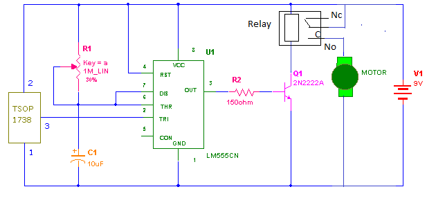
As shown in Circuit Diagram tab2, connect the motor terminals With 9V battery and collector of transistor.
In the receiver the main component is IR-Sensor that is TSOP-1738. This sensor will detect the 38KHz IR light and produce pulse output. The characteristic of this sensor is that it will continuously give high output until IR-Light is not falling on it and when IR-Light falls on it will immediately give law output. so negative pulse will be generated.
Circuit Operation:-
1. When you press switch‘s’ in the transmitter, it will generate IR beam of 38KHz
2.This will be detected by sensor and it will give negative pulse to IC-555
3. This will trigger the monostable operation and give high o/p till the time set by RC component (I have set the time 3- 4 sec.)
4. This high o/p will drive the Motor through transistor and thus will run the toy-car (if car runs in reverse direction just change terminals of DC Motor connected with battery and transistor)
5. When the o/p again goes low it will stop rotating motor and toy-car will stop moving automatically after some distance.
6. So whenever you press the switch on the transmitter the toy-car will move some distance and then stop.
7. Again you press again car will move further and so on and on. One thing should be kept in mind that IR-LED must be pointed toward IR- Sensor. The range is of this remote-control is about 7 meters (if you use standard remote of any TV then the range will be more than 10 meters).
Circuit Diagrams

Filed Under: Electronic Projects

Questions related to this article?
👉Ask and discuss on Electro-Tech-Online.com and EDAboard.com forums.
Tell Us What You Think!!
You must be logged in to post a comment.