This power saving circuit is used to save electricity while ironing by switching OFF the iron box when it is not in use. Once the on time of the circuit is crossed, it produces an alarm. If we press the reset button at the time of alarm, it is switched off and the on time of the circuit is extended to the next 4 minutes. This circuit works as a reminder for those who always forget to turn OFF the iron box in their busy schedule.
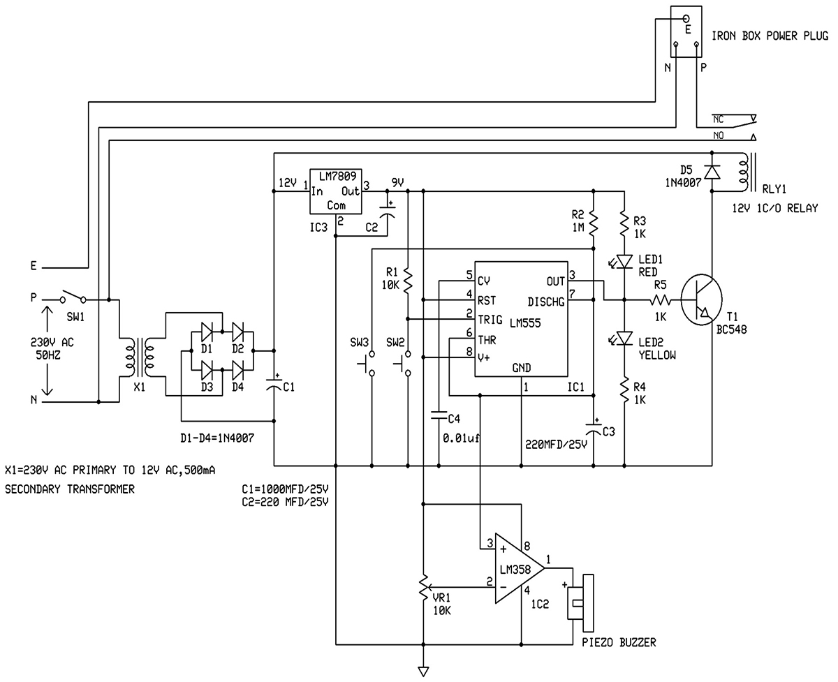
In this, the circuit is built around NE 555(IC1), op-amp LM 358 (IC2) and few other components. IC1 is designed as a standard monostable multivibrator and its trigger pin 2,held high by resistor R1.LM 358, is configured as a comparator. It has both a non-inverting input (pin 3) and an inverting input (pin 2). Inverting pin 2 of IC2 is connected to voltage-divider preset VR1 which aids in varying the reference voltage at pin 2. Buzzer is connected to the output pin 1 which is initially low.
The ‘ON’ time of IC1 is adjusted to 4 minute with the help of capacitor C1and resistor R1. Output pin 3 is fed to the relay driver transistor.
BC 548.
When the switch S1 is pressed, the monostable (IC1) is triggered, the output of IC1 goes high, and the iron box is switched on through relay RL1. Led2 (yellow) is used to indicate that the output is on.
At normal condition, the voltage at the non inverting pin of LM358 (IC1) is less than the voltage at the inverting input of the LM358 and hence the output of the op amp is low.
The timing capacitor C1starts charging and the voltage at the non inverting pin of LM358 (IC1) gets higher than the voltage at the inverting input of the LM358. So the output of the op amp is switched to high. This in turn activates the buzzer, thereby producing a beep sound. If we press the reset switch S2 at the time of alarm, it turns off the alarm, and extends the on time of the circuit to the next 4 minutes. If the reset switch is not pressed at the time of alarm, the iron box is automatically switched off.
Assemble the circuit on a general-purpose PCB and enclose it in a suitable cabinet. Mount switch S1, S2 and the buzzer on the front panel of the box.
COMPONENTS LIST
IC1- NE 555
IC2- LM358
IC3- 7809 REGULATOR IC
T1- BC548
X1- TRANSFORMER 230V/12V/500mA
RLY1- 12V 1C/O RELAY
D1-D5-1N 4007 DIODE
C1- 1000MFD/25V
C2- 220MFD/25V
C3- 220MFD/25V
C4- 0.01MFD
R1- 10K
R2- 1M
VR1- 10K PRESET
SW1- ON/OFF SWITCH
SW2, SW3 – PUSH TO ON SWITCH
R3, R4, R5 1K
LED1- RED
LED2- YELLOW
PIEZO BUZZER

Fig. 1: Prototype of 555 IC based Iron Box Power Saver Circuit
You may also like:


Circuit Diagrams
Filed Under: Circuit Design, Electronic Projects

Questions related to this article?
👉Ask and discuss on Electro-Tech-Online.com and EDAboard.com forums.
Tell Us What You Think!!
You must be logged in to post a comment.