All you might have seen controlling a DC motor using joystick.
· Most of RC toys are DC motor operated and they are controlled using remote controlled joystick. There is a RF transmitter in the remote controlled joystick and in a toy, there is RF receiver that rotates DC motor forward (clockwise) and reverse (anticlockwise)
· The remote controlled robotic vehicles used in military applications also controlled using such joystick connected with laptop or computer
· Unmanned air vehicles like drone, quad copter etc used for air surveillance or aerial photography/videography are the best examples of joystick control
All above are examples of wireless joystick or remote control joystick where joystick is a switch. But there is also one another type of joystick that is resistive joystick. Its like a potentiometer. In the middle position it has fix resistance value but as its moved the resistance increases or decreases. Such joysticks are used in industrial DC motor control. It is used to control direction as well as speed of DC motor.
Here the given circuit also demonstrates use of 2 such resistive joystick and controls 2 DC motors. The circuit is very simple built using op-amps and motor driver chip L293D. It just uses 4 pots as an additional components and it does not required any other additional component. It uses two pots as two joysticks but any 2D resistive joystick can be connected in place of these two pots
Circuit description

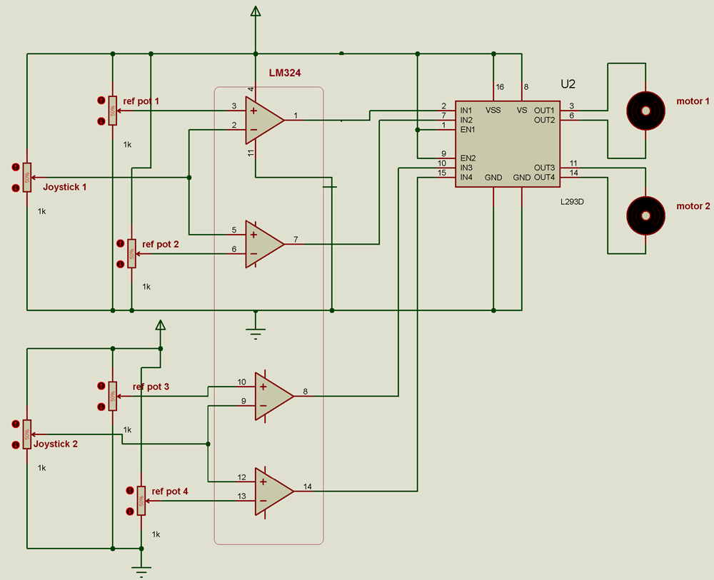
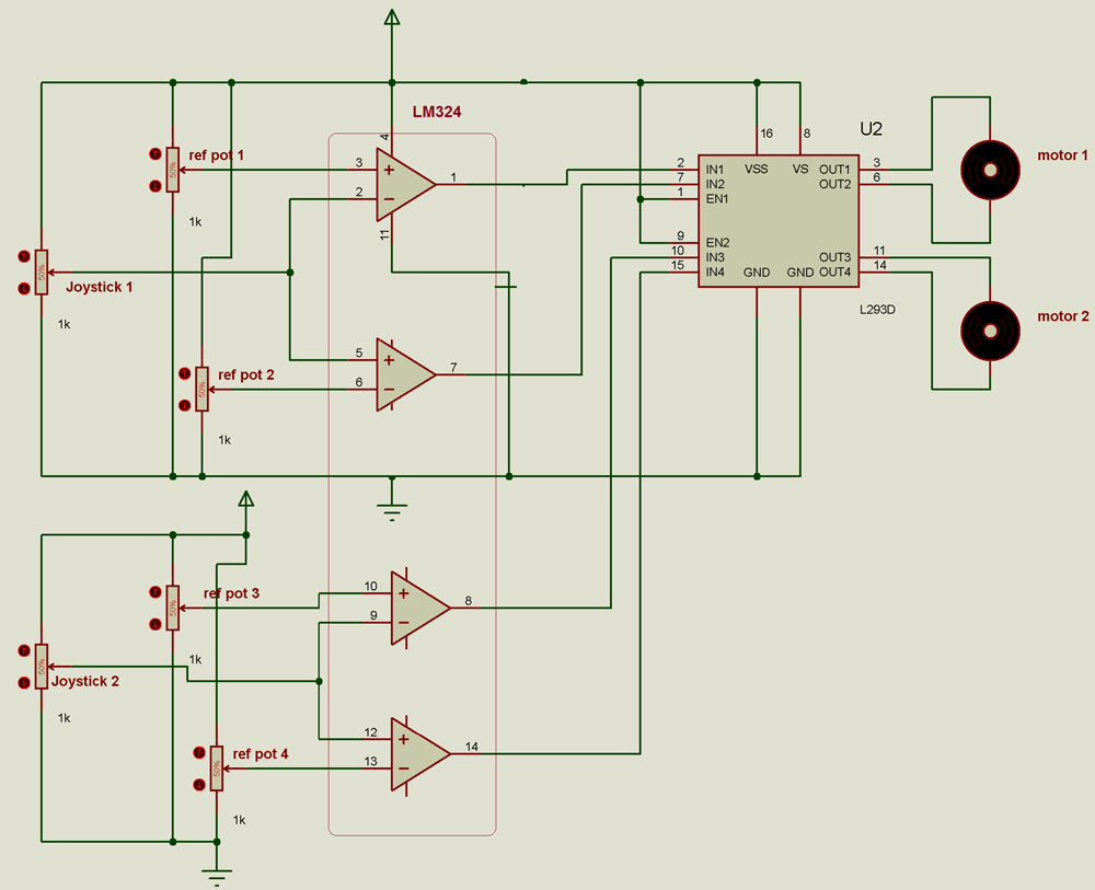
Fig. 1: Circuit Diagram of LM324 OPAM Dual DC Motor Controller
Circuit is very simple made up of quad op-amp chip LM324 and DC motor driver chip L293D. Two pots (1 K) are used as resistive joysticks as shown. Set of 2 op-amps, two reference pots (ref pot) and one joystick is required to control one DC motor. There are two identical sections of op-amps, pots and joystick – 1 section to control 1 DC motor. L293D is used to provide required current to drive motor
· The two fixed terminals of both pots are connected with Vcc and ground as shown
· The middle sliding terminals of ref pot 1 is connected with non inverting input terminal of upper op-amp to provide fixed reference voltage. This reference voltage can be varied/set by changing pot
· Similar to that, the middle sliding terminals of ref pot 2 is connected with inverting input terminal of lower op-amp to set reference voltage for inverting terminal
· The remaining two input terminals of both op-amps are shorted and given input from joystick pot. The joystick pot varies the input voltage given to both terminals
· Two outputs of op-amps drive 1 DC motor through L293D chip. Both outputs are given to two inputs of L293D chip and the DC motor is connected to the output of L293D
· In second section there are same connections. Second section output drives 2nd DC motor through L293D chip as shown
Circuit operation:
· By varying ref pot 1 the reference voltage at non inverting input of upper op-amp can be set. It is set to Vcc / 2
· Similarly ref pot 2 sets reference voltage at inverting input of lower op-amp as Vcc/2
· Both op-amps are working as comparator
· Second input to both comparators is given from joystick. As joystick pot is varied, the second input to both comparators varies. It is also varied to set the input voltage to Vcc/2 at both terminal
· Because op-amps are working as comparator and in both op-amps the reference voltage (set by ref pot) and the input voltage (from joystick pot) are same, the output of both comparators are 0 V. So both inputs to L293D are 0 and so the motor is on rest (stop)
· Now if joystick pot is slightly moved clockwise the voltage at non inverting terminal of lower op-amp and inverting terminal of upper op-amp increases
· So in the lower op-amp the voltage at non inverting terminal becomes more than voltage at inverting terminal. So its output changes to +Vcc
· But in the upper op-amp the voltage at inverting terminal becomes more than voltage at non inverting terminal. So its output remains same 0 V
· Because now the input to L293D becomes IN1 = 0 V and IN2 = +Vcc (1). So DC motor starts rotating in clockwise direction
· Similarly if joystick pot is slightly moved to anticlockwise direction the reverse operation will happen. Now the voltage at non inverting terminal of lower op-amp and inverting terminal of upper op-amp decreases
· So in the upper op-amp the voltage at non inverting terminal becomes more than voltage at inverting terminal. So its output changes to +Vcc
· In the lower op-amp the voltage at inverting terminal becomes more than voltage at non inverting terminal. So its output changes to 0 V
· In this case the input to L293D becomes IN1 = Vcc (1) and IN2 = 0. So DC motor starts rotating in anticlockwise direction
· So the DC motor rotates clockwise or anticlockwise as joystick pot is moved clockwise or anticlockwise
· Similarly the in second section 2nd joystick controls 2nd DC motor. As the joystick pot is rotated clockwise the motor also rotates clockwise and vice versa
Thus with the help of this circuit one can rotate two DC motors forward and reverse using potentiometer as a joystick.
Circuit Diagrams
Project Video
Filed Under: Circuit Design
Filed Under: Circuit Design


Questions related to this article?
👉Ask and discuss on Electro-Tech-Online.com and EDAboard.com forums.
Tell Us What You Think!!
You must be logged in to post a comment.