The DC motor controllers control speed and direction of DC motor. To change the direction of the motor, the supply given to motor has to be reversed and to vary DC motor speed the applied input voltage has to be varied. The PWM method is very popular method to vary DC motor speed. In this method PWM wave is applied to DC motor whose pulse width can be varied. As pulse width increases the average voltage applied to motor increases and vice versa. This means as the pulse width varies the DC motor speed also varies. To change the direction of motor, very popular H-bridge circuit is used. Using H-bridge circuit the supply given to motor can be reversed so the motor will rotate reverse.
Most of the DC motor controllers use PWM to vary motor speed and H bridge circuit to alter its direction. One of the techniques becoming very popular and widely used now a days of DC motor control is to control DC motor through joystick. Using single joystick one can control speed as well as direction of DC motor. When joystick is at centre position the motor is rest. When joystick is moved forward or reverses the motor also rotates forward and reverse. Also the motor speed increases when joystick moved further forward or reverse. Joystick control for DC motor is used in many different applications like
- Remote controlled toys like RC (remote controlled) plane, helicopter, boat, car etc
- Joystick controlled video camera crane
- Industrial Jog* controller
- Robotic arm or robotic vehicle
- Surveillance camera controller
Etc so many application we can list out. In all such applications the DC motor that drives the load is controlled by joystick. In some of the applications only direction of motor is altered (RC toys) while is other application direction and speed both are varied (video camera crane, jog control). The project given here controls speed and direction of DC motor using joystick. A simple potentiometer used here as a joystick. It is built using AVR micro controller ATmega32. It rotates motor forward and reverse as well as varies its speed as joystick is moved.
*note: jog control is used in industries to check DC motor will start rotating in which direction initially when it is connected with load.
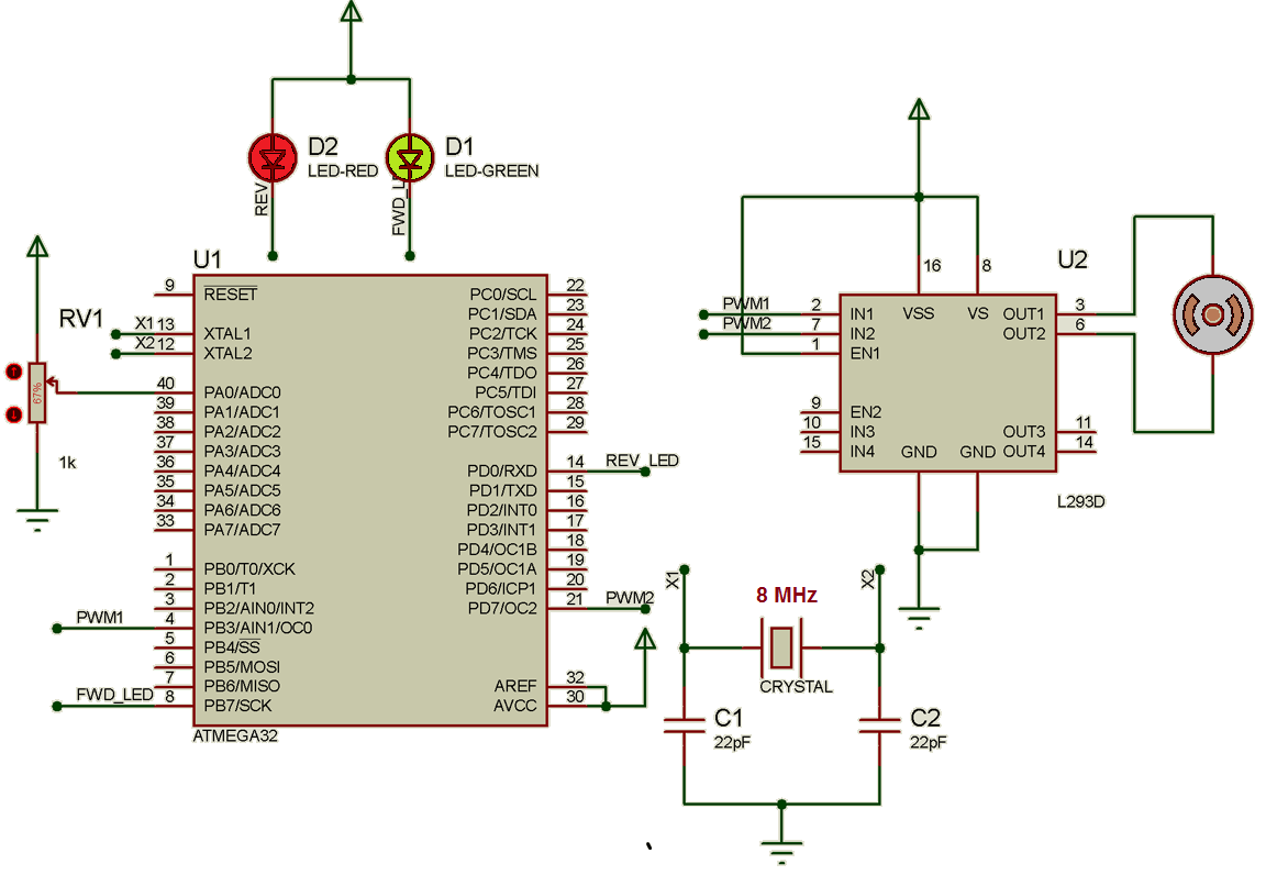
Circuit description:
The circuit is build using two major components AVR micro controller ATMega32 and motor driver chip L293D.
· A 1K pot is connected to 1st channel of ADC input (pin no. 40) as shown. It is connected such that when slider moves the voltage at ADC input varies from 0 to Vcc (5 V)
· Two LEDs – one RED and one Green are connected to PB7 pin (7) and PD0 pin (14) respectively
· Two PWM channel outputs OC0 pin (4) and OC2 pin (21) are connected to two inputs IN1 and IN2 of L293D chip
· The enable input EN1 of L293D is connected to Vcc to enable one half bridge section
· The DC motor is connected to outputs OUT1 and OUT2 of L293D
· One 8 MHz crystal along with two 22 pF capacitors is connected to crystal input pins XTAL1 and XTAL2
Circuit operation:
· Initially pot is turned to exact middle position this makes voltage at ADC pin input equals Vcc / 2 = 2.5 V
· Till the pot is kept at middle position the motor is stop and both LEDs are also off
· As pot is slightly turned clockwise the voltage input at ADC increases and the motor starts rotating forward with low speed. The green LED becomes on to indicate motor is rotating forward
· As pot is turned more clockwise gradually, the motor speed increases gradually
· When pot is fully turned clockwise, the motor attains full speed in forward direction
· When again pot is turned back to middle position, the motor speed gradually decreases and it stops. The green LED is also off
· Now as pot is turned slightly anticlockwise, the motor starts running reverse at slow speed. The RED LED indicates motor is running reverse
· As pot is turned further the motor speed increases and attains maximum speed in reverse direction when pot is turned fully anti clockwise
· To stop motor again, the pot is turned back to middle position
· Thus motor moves forward or reverse as pot is turned clockwise or anticlockwise and also the speed of motor increases as pot is turned more clockwise or anticlockwise
To implement these functionalities a software program is embedded into internal FLASH of ATMega32 micro controller.
Software program:
The software program does following tasks
· Reads analog voltage value on ADC input pin and converts it into digital
· If the digital value is between 510 to 515 then it sends 0 to both PWM output channels and stops the motor
· If the digital value is less than 510 then it generates PWM on OC0 pin to start rotating motor forward. As the value is further decrease the pulse width increases to increase DC motor speed
· Similarly if digital value increases above 515, it generates PWM on OC2 pin to rotate motor reverse. As the value is increased further the pulse width increases that increases motor speed
· It also gives indications on LEDs of motor rotating forward or reverse
The program uses all three timers Timer 0, Timer 1 and Timer 2 of ATMega32. It uses timer 0 and timer 2 to generate PWM to vary speed of DC motor and timer 1 to generate periodic interrupts at specific time interval to read new analog voltage value on ADC input pin.

Fig. 1: Prototype of AVR ATMega32 based Joystick DC Motor Controller
Project Source Code
###
#include <avr/io.h>
#include <util/delay.h>
#include <avr/interrupt.h>
unsigned int adc_value,flag=0;
///////////////////////////////// ADC initialize function ///////////////////////
void adcinitliz()
{
ADMUX = (1<<REFS0); // select reference
ADCSRA =(1<<ADPS2) | (1<<ADPS1) | (0<<ADPS0);
ADMUX=0x00; // select 1st channel
}
void calculate_value()
///////////////////////////// get ADC value and set PWM width//////////////////////
get_adc_value()
{
unsigned int tmp1,tmp2,tmp3,t;
tmp1 = (ADCL & 0x0F); // convert HEX value of ADCL and ADCH
tmp2 = ADCL >> 4; // into decimal
tmp3 = (ADCH & 0x0F);
tmp2 = tmp2*16;
tmp3 = tmp3*256;
t = tmp1+tmp2+tmp3;
adc_value = t; // get decimal equivalent value
if(t<115) OCR0 = 245; // set width of PWM as per
else if((t>=115) && (t<215)) OCR0 = 0xCC; // ADC vlaue
else if ((t>=215) && (t<315)) OCR0 = 0x99;
else if ((t>=315) && (t<415)) OCR0 = 0x66;
else if ((t>=415) && (t<=510)) OCR0 = 0x33;
else if((t>=515) && (t<615)) OCR2 = 0x33;
else if ((t>=615) && (t<715)) OCR2 = 0x66;
else if ((t>=715) && (t<815)) OCR2 = 0x99;
else if ((t>=815) && (t<915)) OCR2 = 0xCC;
else if(t>=915) OCR2 = 245;
}
/////////////////////////////// initialize timer 1 /////////////////////////////
void timer1_init()
{
TCCR1B |= (1 << CS11); // select clock
TCNT1 = 0; // start count from 0
TIMSK |= (1 << TOIE1); // enable timer 1 interrupt
sei();
}
//////////////////////////// timer 1 overflow interrupt subroutine ///////////////
ISR(TIMER1_OVF_vect)
{
ADCSRA = (1<<ADEN) | (1<<ADSC); // start conversion
while(!(ADCSRA & (1<<ADIF))); // wait till conversion end flag is set
ADCSRA = (1<<ADIF);
flag=1; // set user flag to 1
}
/////////////////////////////////// main function ////////////////////////////////
int main()
{
int flag=0; // declare and initialize user flag
DDRB=0x48; // set LED pin and PWM pin as output for
PORTB=0x40; // PORTB and PORTD
DDRD=0x81;
PORTD=0x01;
adcinitliz(); // initialize ADC
timer1_init(); // initialize timer 1
ADCSRA = (1<<ADEN) | (1<<ADSC); // start conversion
while(!(ADCSRA & (1<<ADIF))); // wait till end of conversion
ADCSRA = (1<<ADIF);
get_adc_value(); // get ADC value in decimal
///////////////////////////////// continuous loop /////////////////////////
while(1)
{
while(flag==0) // wait till ADC conversion ends and user
{ // flag is set
get_adc_value(); // get ADC value in decimal
if(adc_value>515) // if ADC value is more than 515
{
TCCR0=0x00; // stop PWM on channel 0
TCCR2=0x6C; // start PWM on channel 1
PORTB &= 0xB7; // green LED on
PORTD |=0x01; // red LED off
}
else if(adc_value<510) // if ADC value is less than 510
{
TCCR0=0x6B; // start PWM on channel 0
TCCR2 = 0x00; // stop PWM on channel 1
PORTD &= 0x7E; // red LED on
PORTB |= 0x40; // green LED off
}
else if((adc_value>=510) && (adc_value<=515)) // if ADC value is in
{ // middle
TCCR0=0x00; // stop both PWM
TCCR2=0x00;
PORTB=0x40; // both LEDs off
PORTD=0x01;
}
flag=0; // clear user flag for new value
}
}
}
###
Circuit Diagrams
Project Video
Filed Under: Electronic Projects
Filed Under: Electronic Projects

Questions related to this article?
👉Ask and discuss on Electro-Tech-Online.com and EDAboard.com forums.
Tell Us What You Think!!
You must be logged in to post a comment.