Atmega/Arduino Timers
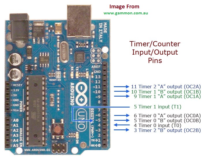
Arduino Pins associated with its timers
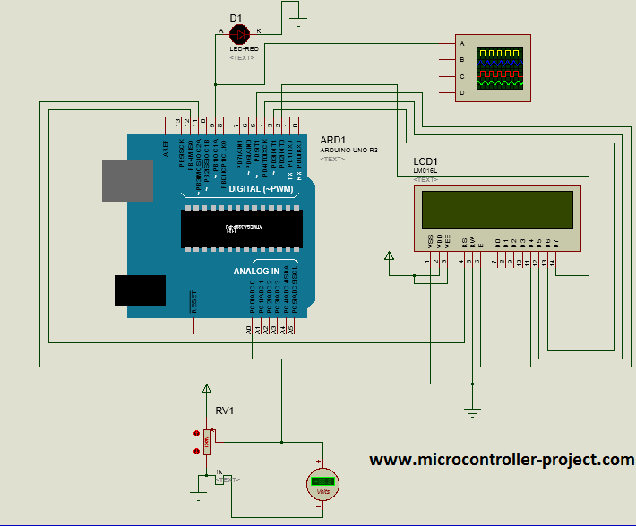
Arduino variable frequency signal output – Diy project
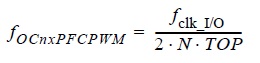
Arduino variable frequency generation formula
|
Where
|

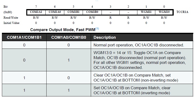
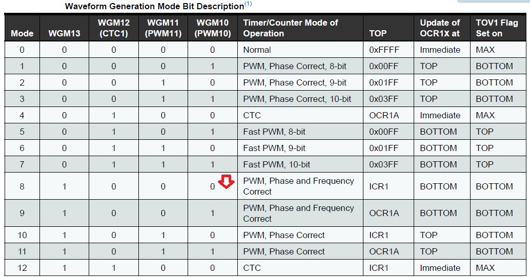
For this to happen we have to set some bits in timer registers TCCR1A and TCCR1B. In TCCR1A set the mode of the timer. I set Fast PWM. By selecting bits COM1A1,COM1B1. Selecting these bits will make your pins OC1A and OC1B to output fast PWM.
For generating 10Hz signal. You input 4.8 volts.
Code Flow
Pinput will be Pinput=1015; // 4.8 volts at arduino analog pin reading
Pinput=(1015/0.0113); —> Pinput=89823;
count= 10000+89823;
count=99823; //If we put this count value back in above formula we get 10.01 Hz frequency
The maximum analog channel can read is 1023 and Pinput value goes to 1023/0.0113=90530 or count=10000+90530= 100530. Which lower down the frequency to 9.9 Hz and since we want to remain in the bracket of 10 to 100Hz so we can not go more high. I hope 0.0113 makes sense now. Its just a value to remain in 10000 to 100000 bracket.
Watch the Project video here…
Filed Under: Knowledge Share, Microcontroller Projects

Questions related to this article?
👉Ask and discuss on Electro-Tech-Online.com and EDAboard.com forums.
Tell Us What You Think!!
You must be logged in to post a comment.