When ever you want to drive heavy loads with a small TTL signal you use a transistor, bjt or a mosfet. In case the circuit becomes complex and you need to drive load with two, three or four TTL signals you use a combination of transistors or mosfet to provide high power output to load. For example motors dc or stepper or servo require high power and 2, 3 control signals for rotation direction change and speed control. This transistor or mosfet combination is know as H-bridge circuit. Making a H-bridge circuit on bread board or pcb(printed circuit board) requires many wires to be connected and it seems like a mess also the circuit takes too much space. Luckily this issue can be over come by using l293d ic.
L293d ic is same like an h bridge circuit with two channels. It has two half h bridge circuits residing in it. You can use it to drive uni polar, bi polar stepper motors, dc motors or even servo motors. The individual two channels can be use stand alone to drive solenoids/relays. A single channel can be used to drive a dc motor in forward(clock wise) or back word(anti clock wise) direction. Hence we can drive two dc motors with l293d. It can also be used to output a pwm (pulse width modulation) signal.
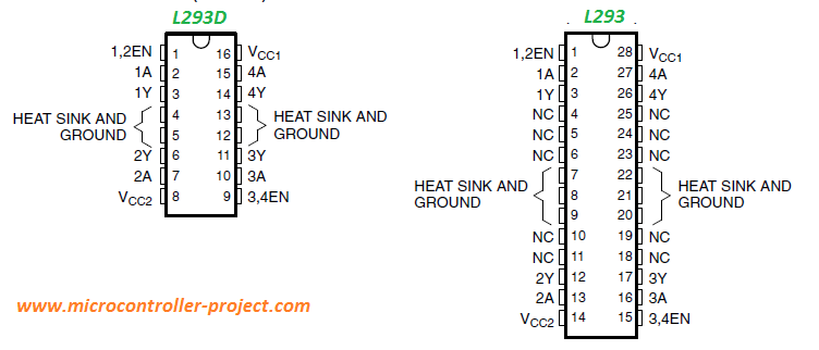
The ic came in two different versions L293 and L293D. Both have same number of operational pins with same pin names. But differ in voltage and current supply and control specifications. L293 can output more current. But the disadvantage is it has greater number of pins than L293D.
L293DTotal number of pins = 16
Ic Operating voltage = 5 – 7 v Input voltage = 4.5 – 36 v Output voltage = 4.5 – 36 v Continuous Output Current = 600 mA or 0.6 A |
L293Total number of pins = 28
Ic Operating voltage = 5 – 7 v Input voltage = 4.5 – 36 v Output voltage = 4.5 – 36 v Continuous Output Current = 1 A |
L293 and L293D Pin out defination
1,2EN: To activate the channel 1 we supply +5v to this pin.
3,4EN: To activate the channel 2 we supply +5v to this pin.
Vcc1: Input voltage to derive the internal circuit (darligton array) = 4.5 to 5 v
Vcc2: Supply/Output to appear at output = 4.5 to 36 v
1A: Channel-1 Input Pin
2A: Channel-1 Input Pin
1Y: Channel-1 Output Pin
2Y: Channel-1 Output Pin
3A: Channel-2 Input Pin
4A: Channel-2 Input Pin
3Y: Channel-2 Output Pin
4Y: Channel-2 Output Pin
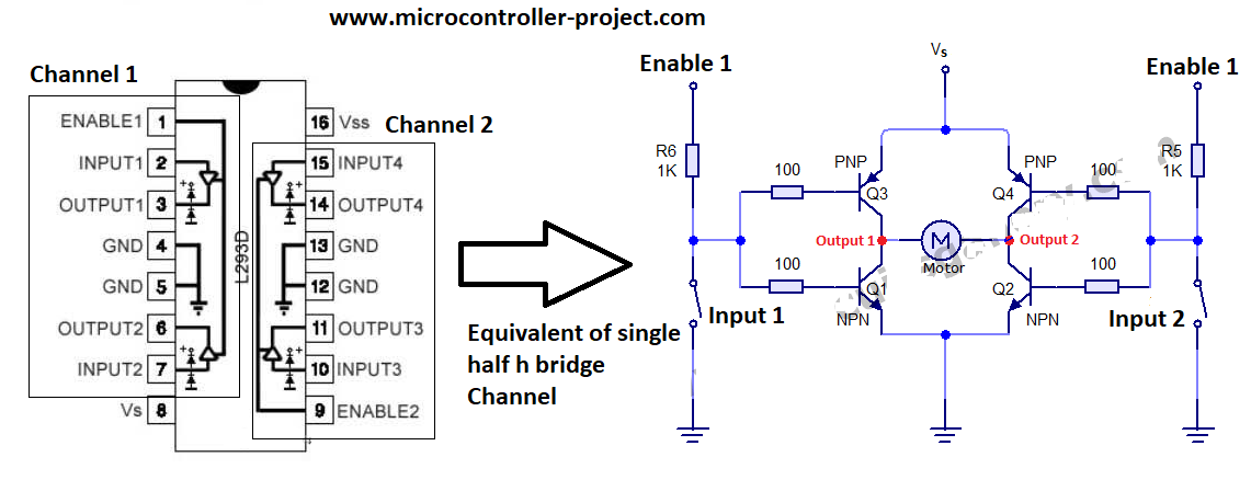
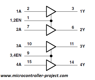
1A and 2A are control pins of channel 1. 1Y and 2Y are output pins of channel 1. Similarly 3A and 4A are input pins for channel 2 and 3Y, 4Y are output pins for channel 2. 1,2En are enable pins of channel 1. 3,4 EN are enable pins of channel 2. Individual l293d motor driver channel equivalent circuit is given below.
L293d Channels
How l293d motor driver individual channel works?
|
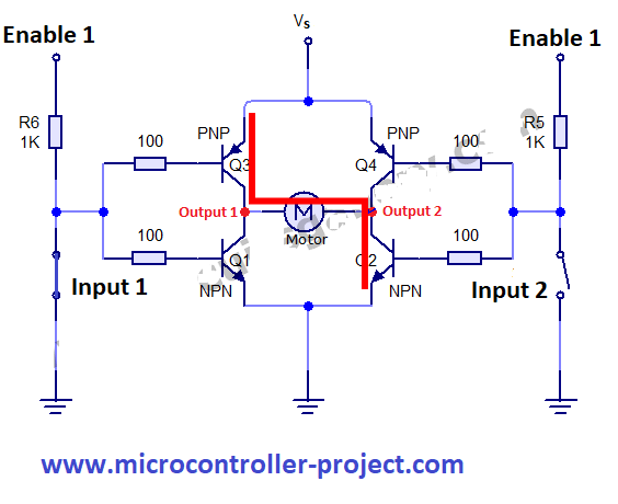
When input 1 is closed and input 2 is opened transistor Q3 and Q2 are opened/operational, allowing current to flow from them. The motor connected across the output 1 and 2 now starts rotating. The motor direction of rotation is clock wise. One PNP and one NPN transistor is activated when one input is closed and other is opened.
Note: Enable 1 is also at high potential. Means it is supplied +5 volts. Vs is supplied 0 – 36 volts depending on the motor requirements. |
|
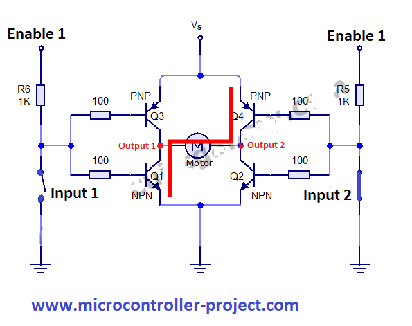
When input 1 is opened and input 2 is closed transistor Q4 and Q1 are operational. Current start flowing through this path and the motor starts moving in the anti clock wise direction. Enable is still at high potential and vs is supplied battery required voltage.
If both the input 1 and input 2 are opened or closed to current path will be established and motor will not rotate. If any input is closed and enable is not at high potential than still the circuit will not work. Enable is a master pin and controls the whole circuit. |
A pwm(pulse width modulated) signal can be applied to input pins to control the speed of motor. Enable pin can also be utilized to control the motor rotation speed. By enabling and disabling the enable pin, individual channels can be enable/disable rapidly producing a pulse width modulated signal which alternatively lowers or increases the rotation speed of dc motor.
L293 and L293D Internal structure
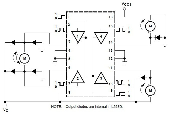
Above the internal structure of l293d is shown. One is taken from datasheet by stmicroelectronics and other is from Texas instruments. In both the above circuits you can see the internal structure is same. Their are total four channels. The diodes are fly wheel/kick back diodes that eliminates any induced emf by motors,solenoids and relay etc connected at output. The circuit by Texas instruments show how to run dc motors with l293d and how the polarity works.
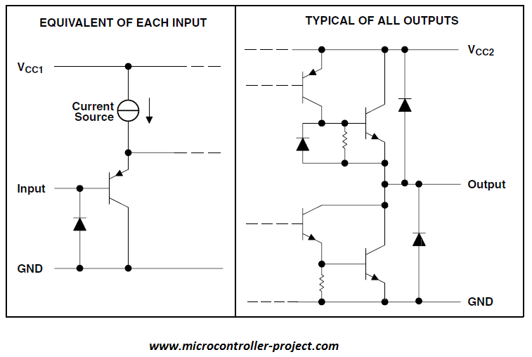
Above the equivalent of input circuit and output circuit is shown. Input side is simple just a transistor with a protection diode. At output side we have a darlington circuit with high current gain and protection diodes. The rotation of motors connected at the output of l293d and the input output truth table is shown below. Single direction driven motor and dual direction control motors circuit and truth table is given below. Single direction driven motor uses only one channel. Where as direction control motor occupies two channels.
Check Out a some Projects Related to L293D h bridge motor controller and 89c51, arduino and stm32 microcontroller.
Conclusion
|
An external unit is required to control the function of the l293d motor driver, like microcontroller, fpga etc. L293d is used in many circuits, it is popular in toy industry. You can find it in many toys such as rc cars, helicopters etc. Many diy kits are available in market to start working with l293d. You can find cheap l293d diy circuit modules on eBay and Alibaba.
|
Filed Under: Microcontroller Projects, STM32.




Questions related to this article?
👉Ask and discuss on Electro-Tech-Online.com and EDAboard.com forums.
Tell Us What You Think!!
You must be logged in to post a comment.