Engineers Garage

  • Electronic Projects & Tutorials
    • Electronic Projects
      • Arduino Projects
      • AVR
      • Raspberry pi
      • ESP8266
      • BeagleBone
      • 8051 Microcontroller
      • ARM
      • PIC Microcontroller
      • STM32
    • Tutorials
      • Audio Electronics
      • Battery Management
      • Brainwave
      • Electric Vehicles
      • EMI/EMC/RFI
      • Hardware Filters
      • IoT tutorials
      • Power Tutorials
      • Python
      • Sensors
      • USB
      • VHDL
    • Circuit Design
    • Project Videos
    • Components
  • Articles
    • Tech Articles
    • Insight
    • Invention Stories
    • How to
    • What Is
  • News
    • Electronic Product News
    • Business News
    • Company/Start-up News
    • DIY Reviews
    • Guest Post
  • Forums
    • EDABoard.com
    • Electro-Tech-Online
    • EG Forum Archive
  • DigiKey Store
    • Cables, Wires
    • Connectors, Interconnect
    • Discrete
    • Electromechanical
    • Embedded Computers
    • Enclosures, Hardware, Office
    • Integrated Circuits (ICs)
    • Isolators
    • LED/Optoelectronics
    • Passive
    • Power, Circuit Protection
    • Programmers
    • RF, Wireless
    • Semiconductors
    • Sensors, Transducers
    • Test Products
    • Tools
  • Learn
    • eBooks/Tech Tips
    • Design Guides
    • Learning Center
    • Tech Toolboxes
    • Webinars & Digital Events
  • Resources
    • Digital Issues
    • EE Training Days
    • LEAP Awards
    • Podcasts
    • Webinars / Digital Events
    • White Papers
    • Engineering Diversity & Inclusion
    • DesignFast
  • Guest Post Guidelines
  • Advertise
  • Subscribe

Interfacing Lcd(8×1,8×2,10×1,10×2, 16×2, 16×4, 20×1, 20×2, 40×1,40×2) in 4 Bit Mode with Microchip Pic16f877A Microcontroller

By EG Projects July 28, 2019

In this project i am going to interface 16×2 lcd display in 4-bit mode with Microchip Pic16f877 microcontroller. We can interface any size of character lcd display (8×1,8×2,10×1,10×2, 16×2,16×2,16×4,20×1,20×2,40×1,40×2 etc) in 4-bit mode with pic microcontrollers. In 4-bit interface mode only 4 lcd data lines are used to display data on lcd screen. Usually lcd is interfaced in 4-bit mode with microcontrollers to save I\O pins of microcontrollers. Before beginning any further i assume that you know difference between 4-bit and 8-bit lcd interfacing mode with microcntrollers. If not just take the below simple tutorial. Tutorial will help you in understating the basic difference, pros and cons of both the modes. It will also help you in understanding the code below easily.

  • Difference between 4-bit and 8-bit lcd working mode.​​

16×2 lcd in 4-bit mode with pic microcontroller – Project requirements

  • 16×2 character lcd.
  • Pic 16f877.
  • Potentiometer (For setting lcd contrast).
  • Crystal(20MHz).
  • Connecting wires.
  • Bread board or PCB for the circuit.
  • Power Supply. ​​

16×2 lcd in 4-bit mode

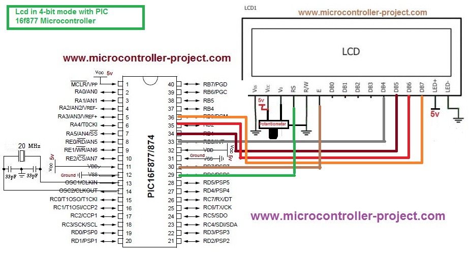
In 4-bit mode only 4-bit data is send to lcd at a time. Since 8-bit microcontrollers contains data in 8-bit form so we divide our data in to two nibbles(1-nibble=4-bits). First higher 4-bits(nibble) is send to lcd and then the lower 4-bits(nibble) with enable stroke signal. Only D4,D5,D6,D7 data pins of 16×2 lcd are used in 4-bit interface mode. D1,D2,D3,D4 are left empty. D4 is our least significant bit and D7 is highest significant bit in 4-bit interface mode. A typical interfacing diagram is given at the right side. 
Lcd interfacing with Pic Microcontroller in 4 Bit Mode

Lcd interfacing with Pic Microcontroller in 4 Bit Mode

Interfacing 16×2 Lcd with pic microcontroller in 4-bit mode – Project circuit diagram

Interfacing 16×2 lcd with Pic16f877 microcontroller is simple, if you have taken the above tutorial. The circuit of the project is also very simple. Port-B first 4 bits (RB0,RB1,RB2,RB3) of Pic16f877 microcontroller are used to send 4-bit data and commands to lcd. These four Pins(RB0,RB1,RB2,RB3) are Connected to four data pins of 16×2 lcd(D4,D5,D6,D7). Port-D pin# 5 is connected to rw(read-write) pin of lcd. Port-D pin# 6 is connected to rs(register select) pin of lcd. Port-D pin# 7 is connected to en(Enable) pin of 16×2 lcd. If you are newbie and have to idea about the working and pin configuration of lcd. Below is a good tutorial.

  • 16×2 lcd working pin configuration and internal structure.

​
Taking the upper tutorial will led you know how 16×2 lcd works & how to configure it.The circuit diagram of the project is given below. 

Interfacing 16x2 Lcd in 4-bit mode with pic16f877a microcontroller

Interfacing 16×2 Lcd in 4-bit mode with pic16f877a microcontroller

Interfacing 16×2 lcd in 4-bit mode with pic microcontroller- Project code

Coming to the code portion. Code is written in c language using Mp-lab ide by Microchip and high tech c compiler is used for compiling and generating hex code file. First header file htc.h is included. This header file must be included if you are using high tech c compiler for compilation of code. delay() function is used here for generating some delay. You can also use predefined delay function like __delay_us() etc.

Some functions and their working.
It is assumed that you know all about operators like (>>,& etc) and their functions. 

lcdcmd()

  • This function is sending high and low bytes of a command one by one to llcdcmd() function.
  • The statement llcdcmd(c>>4); is moving our high Byte (four high bits) to right and then sends them to llcdcmd function.
  • The statement llcdcmd(c); is sending our low Byte(four low bits) to llcdcmd function.

display()

  • This function is also working in the same way as lcdcmd(). The difference is it is sending data to ddisplay() function.

llcdcmd()
This function is separating four bits from our command and puts them on RB0,RB1,RB2,RB3 line and then sends them to lcd. The following instructions are separating four bits.
RB0=(value >> 0) & 0x01;
RB1=(value >> 1) & 0x01;
RB2=(value >> 2) & 0x01;
RB3=(value >> 3) & 0x01;

ddisplay()
This function is separating four bits from our 8-bit data and puts the 4-bit data on RB0,RB1,RB2,RB3 pins and then sends them to lcd. Following instructions are separating four bits.
RB0=(value >> 0) & 0x01;
RB1=(value >> 1) & 0x01;
RB2=(value >> 2) & 0x01;
RB3=(value >> 3) & 0x01;

If you dont know what is meant by commands and data send to 16×2 lcd here is a simple tutorial.

  • Difference between commands and data send to lcd.

In the main function i first called lcdint() function. This function is initializing our lcd. Refer to the data sheet of lcd if you dont know what is lcd initialization. Then i am sending data to 16×2 lcd which i want to display on lcd screen. I am displaying word “Microcontroller” on lcd display screen. 

Note: Although i declared the R/W pin in code (RD-5) but i am not using it. I made the lcd R/W pin directly ground. So now it remains always in write mode.
Download the project files and code with simulation. Simulation is made in proteaus and code is written using MP-lab ide and high tech c compiler. Please give us Your feed back on the project. If you have any questions regarding post or you dont understand any instruction please leave your comments below.

Filed Under: Microcontroller Projects, PIC Microcontroller


Next Article

← Previous Article
Next Article →

Questions related to this article?
👉Ask and discuss on Electro-Tech-Online.com and EDAboard.com forums.


Tell Us What You Think!! Cancel reply

You must be logged in to post a comment.

EE TECH TOOLBOX

“ee
Tech Toolbox: 5G Technology
This Tech Toolbox covers the basics of 5G technology plus a story about how engineers designed and built a prototype DSL router mostly from old cellphone parts. Download this first 5G/wired/wireless communications Tech Toolbox to learn more!

EE Learning Center

EE Learning Center
“engineers
EXPAND YOUR KNOWLEDGE AND STAY CONNECTED
Get the latest info on technologies, tools and strategies for EE professionals.

HAVE A QUESTION?

Have a technical question about an article or other engineering questions? Check out our engineering forums EDABoard.com and Electro-Tech-Online.com where you can get those questions asked and answered by your peers!


RSS EDABOARD.com Discussions

  • Finding past posts on edaboard?
  • I think i have devised a new type of "super_transformer" for the Electricity grid?
  • Industrial Relay Board Design for Motorcycle Use
  • sequence detector FSM design
  • Need suggestions in task NI6363 retrigger (analog trigger)

RSS Electro-Tech-Online.com Discussions

  • Sump pit water alarm - Kicad 9
  • Pic18f25q10 osccon1 settings swordfish basic
  • Anyone jumped from Easyeda std to Easyeda pro?
  • turbo jet fan - feedback appreciated.
  • More fun with ws2812 this time XC8 and CLC

Featured – LoRa/LoRaWan Series

  • What is the LoRaWAN network and how does it work?
  • Understanding LoRa architecture: nodes, gateways, and servers
  • Revolutionizing RF: LoRa applications and advantages
  • How to build a LoRa gateway using Raspberry Pi
  • How LoRa enables long-range communication
  • How communication works between two LoRa end-node devices

Recent Articles

  • How IoT network topologies work
  • The top five AI startups to watch in 2025
  • STMicroelectronics unveils SoC based on secure MCU
  • Nexperia’s 48 V ESD diodes support higher data rates with ultra-low capacitance design
  • Taoglas releases Patriot antenna with 18 integrated elements covering 600 to 6000 MHz

EE ENGINEERING TRAINING DAYS

engineering

Submit a Guest Post

submit a guest post
Engineers Garage
  • Analog IC TIps
  • Connector Tips
  • Battery Power Tips
  • DesignFast
  • EDABoard Forums
  • EE World Online
  • Electro-Tech-Online Forums
  • EV Engineering
  • Microcontroller Tips
  • Power Electronic Tips
  • Sensor Tips
  • Test and Measurement Tips
  • 5G Technology World
  • Subscribe to our newsletter
  • About Us
  • Contact Us
  • Advertise

Copyright © 2025 WTWH Media LLC. All Rights Reserved. The material on this site may not be reproduced, distributed, transmitted, cached or otherwise used, except with the prior written permission of WTWH Media
Privacy Policy

Search Engineers Garage

  • Electronic Projects & Tutorials
    • Electronic Projects
      • Arduino Projects
      • AVR
      • Raspberry pi
      • ESP8266
      • BeagleBone
      • 8051 Microcontroller
      • ARM
      • PIC Microcontroller
      • STM32
    • Tutorials
      • Audio Electronics
      • Battery Management
      • Brainwave
      • Electric Vehicles
      • EMI/EMC/RFI
      • Hardware Filters
      • IoT tutorials
      • Power Tutorials
      • Python
      • Sensors
      • USB
      • VHDL
    • Circuit Design
    • Project Videos
    • Components
  • Articles
    • Tech Articles
    • Insight
    • Invention Stories
    • How to
    • What Is
  • News
    • Electronic Product News
    • Business News
    • Company/Start-up News
    • DIY Reviews
    • Guest Post
  • Forums
    • EDABoard.com
    • Electro-Tech-Online
    • EG Forum Archive
  • DigiKey Store
    • Cables, Wires
    • Connectors, Interconnect
    • Discrete
    • Electromechanical
    • Embedded Computers
    • Enclosures, Hardware, Office
    • Integrated Circuits (ICs)
    • Isolators
    • LED/Optoelectronics
    • Passive
    • Power, Circuit Protection
    • Programmers
    • RF, Wireless
    • Semiconductors
    • Sensors, Transducers
    • Test Products
    • Tools
  • Learn
    • eBooks/Tech Tips
    • Design Guides
    • Learning Center
    • Tech Toolboxes
    • Webinars & Digital Events
  • Resources
    • Digital Issues
    • EE Training Days
    • LEAP Awards
    • Podcasts
    • Webinars / Digital Events
    • White Papers
    • Engineering Diversity & Inclusion
    • DesignFast
  • Guest Post Guidelines
  • Advertise
  • Subscribe