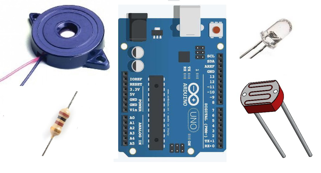
Piezo buzzer
LDR(Light dependent resistor)/Photoresistor
In our project we are also going to measure the intensity of light with ldr(light dependent resistor). Now how we are going to measure it? See the diagram on below.
The voltage appearing across the 100 k resistor is read by the analog pins of arduino and translated for further use(controlling buzzer arduino and led fade mechanism).
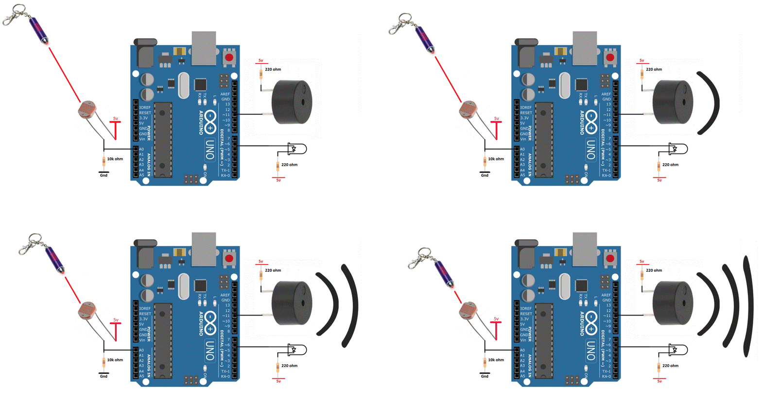
Project Circuit diagram
Arduino buzzer one leg is connected to arduino pin#11 and the other is pulled high. Led positive leg is connected to arduino pin#6 and the other end is pulled high. 5 volts supplied to buzzer and led can be from the arduino 5v pin. 220 ohm resistor in series with the buzzer and led is used for current limiting purpose.
LDR and 10 k resistor voltage divider circuit middle point is connected to analog channel 0 of arduino uno. Ldr input 5 volts can also be supplied with the arduino 5 volt output rail. Circuit diagram of the project is given below.
In setup function arduino serial port is also initialized at 9600 baud rate. Arduino serial port is initialized to see the voltage measurement by analog channel 0 to which LDR output is connected. Serial.begin(9600) statement is initialing the arduino serial port.
In the loop function first i am reading the LDR intensity light value. The statement int senValue=analogRead(sensor) is reading the LDR output voltage across 10 k resistor. The read value is stored in senValue variable.
- Arduino is a 5 volt tolerant device. Its gpio pins can output 5 volt TTL signal. Similarly its gpio pins can be exposed to 5 v TTL signal as input. Higher than 5 v may destroy the gpio pin. So your input voltage to arduino pins must remain between 0-5 volts. I supplied 5 volt to LDR keeping in mind the above constraint.
- Arduino analog channel can also read max 5 volts. Arduino ADC(Analog to digital channel) is 10 bit wide or its resolution is 10 bit. Means it can output value up to 1024. 1024 represents 5 volts. 512 represents 2.5 volts and vise versa.
- So if voltage across the 10 k resistor is 2 volts than the analog channel 0 of arduino will read it and provide us an integer value of 410. [ (410/1024)*5v = 2v ].
The same above strategy is applied in the code. When the voltage across 10 k resistor increases 1.5 volts(ADC value 310) then the buzzer and led are activated and are driven with the same voltage that appears across the 10 k resistor. The if statement in the code is checking 1.5 volts or 310 integer value by ADC. Buzzer and LED will operate only on the voltages greater than 1.5 volts.
- Unlike arduino ADC the arduino pwm provides 8 bit resolution. So in analogWrite(*, senValue/4) function in code i am dividing the senValue by 4 to bring the senValue in 8 bit resolution 0-255. I hope it makes sense to you.
More advanced projects involving Buzzer and a microcontroller. Click the below buttons to visit the projects. Source code and circuit diagram of each project is free.
You may also like:
Filed Under: Arduino., Electronic Projects, More Editor's Picks





Questions related to this article?
👉Ask and discuss on EDAboard.com and Electro-Tech-Online.com forums.
Tell Us What You Think!!
You must be logged in to post a comment.