Getting started with microcontroller and leds is a basic project from where newbies start their learning of new microcontrollers. After on they start to find the different features it offers and what are its advantage over the other microcontrollers. We are gone through Getting started with stm32f103 microcontroller and now its time to learn about its other features. Unlike other 8 bit microcontrollers stm32f103 is a 32 bit microcontroller offering greater speed with greater Input/Output features. Its ports are 16-bit wide. For this tutorial i decide to work with its ports. This simple tutorial is about controlling led bar array lights with stm32f103 microcontroller. For this project is used a pre-assembled stm32 board. Particular microcontroller on board is stm32f103C8T6. Stm32cubeMx is used to initialize the microcontroller ports, pins and registers etc. Keil uvision 5 is used with HAL libraries for code building and compiling.
Stm32f103 has 3 input/output ports. Its Port-A is 16-bit wide(From now own we will only discuss port-a). I decided to connect an 8-bit led array bar to this port and see how to manipulate the port in code. Working and understanding HAL libraries is tough and time consuming. Finally i was able to manipulate the port and i am going to present the code to newbies in this tutorial.
Stm32f103 has 3 input/output ports. Its Port-A is 16-bit wide(From now own we will only discuss port-a). I decided to connect an 8-bit led array bar to this port and see how to manipulate the port in code. Working and understanding HAL libraries is tough and time consuming. Finally i was able to manipulate the port and i am going to present the code to newbies in this tutorial.
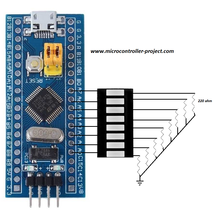
Led bar with stm32f103 microcontroller
Project circuit diagram is given above. I used Port-A first 8 pins. The rest 8 i left because in the above board they are not fully exposed. Some pins are not present on board, may be due to the small size of board its impossible to expose all the pins out. One can see pin#13 and 14 of port-a are not exposed on the above board. Anyhow i connected the led bar anode side with the port-a pins of stm32 microcontroller. Cathode side is connected to ground with 220 ohm resistors. Please make sure if you are going to build the above circuit first identify the polarity of the led bar then insert it in the circuit.
For saving microcontroller power one can connect the anode side to led array with external power or 3.3 volt output of stm32 and cathode with the stm32 pins with resistance in series. This will be the best practice. I checked the above circuit configuration it worked but it will not be advised to build the same circuit if you are also utilizing other features of stm32 microcontroller.
For saving microcontroller power one can connect the anode side to led array with external power or 3.3 volt output of stm32 and cathode with the stm32 pins with resistance in series. This will be the best practice. I checked the above circuit configuration it worked but it will not be advised to build the same circuit if you are also utilizing other features of stm32 microcontroller.
Coming to the code portion. The main part in code is writing to the ports. The statement
GPIOA->ODR = 0x0001;
is writing to port-a. In the above statement ODR is a 16-bit register used to write to pins on individual ports. This register is assessed with the port name. 0x0001 is a hexadecimal command. If we translate it in to binary it becomes 0000000000000001. Writing this binary value to port-a means. Pin#1 of port-a becomes high and rest of the pins remain low OR in other words first led will switch on and the rest remain off. 0x0001 is followed by 0x0003, 0x0007 and so on. All these commands are switching on leds one by one. At the end 0x0000 switches off all the leds. A quarter second delay is inserted between each command to visibly see the leds turning on one by one.
One second delay after each successive loop execution of led array is to give controller some rest. Though its not necessary to give delay here. Since microcontrollers are designed for high frequency output I just inserted it to see it by naked eye that the system is properly working and according to our our logic. I used ST-Link v2 to upload code to microcontroller.
If you are unable to understand how ODR register is accessed and used? Where is its documentation? What about other ways to access the pins of stm32 microconntroller. Then take a small tutorial it will clear all the above answers. Link is below
If you are unable to understand how ODR register is accessed and used? Where is its documentation? What about other ways to access the pins of stm32 microconntroller. Then take a small tutorial it will clear all the above answers. Link is below
Download the project code. Stm32cubemx configuration and keil uvision 5 files are included in the folder. If you have any questions and queries please write them below in the comments section.
Filed Under: Microcontroller Projects, STM32.

Questions related to this article?
👉Ask and discuss on EDAboard.com and Electro-Tech-Online.com forums.
Tell Us What You Think!!
You must be logged in to post a comment.