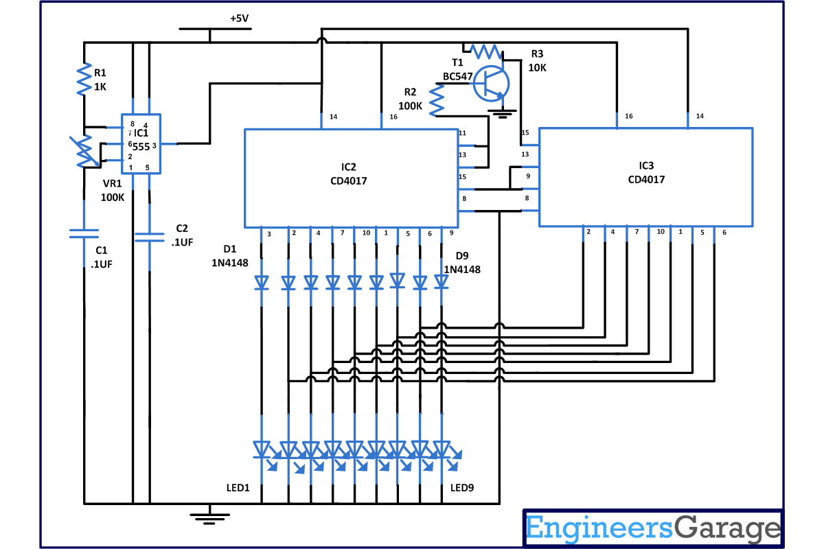
This simple pendulum circuit drives 9 LED's in "pendulum mode". It will provide a eye catching appearance as LED first move in one direction and again move back in same direction. Means LED's are moving back and forth like pendulum. You can use this circuit for decoration purpose or can be used in emergency when your car broke down and you require help.
[[wysiwyg_imageupload:8574:]]
Fig. 1: Prototype Of Pendulum Circuit On Breadboard
The circuit is based on two IC’s namely NE555 and CD4017 with few more components where 555 timer IC is wired as an astable oscillator. CD4017 is a CMOS counter/ divider IC which takes clock signal from the clock input and turns on
The 10 output in sequence, each time when it receives clock input pulses. It is a popular IC and is extremely useful in various projects like Light Chaser, Matrix Die.
In this circuit NE555 astable generates a clock for the circuit, which provides a oscillating wave to the output pin 3 of IC1. You can vary the speed of oscillation with the help of VR1. The frequency of oscillation of 555 timer can be calculated by-
f=1.44/(R1+2*(VR1)*C1)
In this circuit, we have used two decade counter so they will count from 0 to 16. In this counting from 0 to 9 is done by IC2 and remaining counting is done by IC3 with the help of diode.
Now when power supply is given to 555 timer, output from pin 3 of IC1 is provided to CD4017 decade counter pin 14, which provides a clock pulse for the working of IC2. Here after receiving the clock input, CD4017 starts its counter from zero (as it has inbuilt counter). It advances one by one each time pin 14 goes high. First we get output from pin 3 that is Q0 and LED1 will glow and then from pin 2, LED2 will glow and so on. When the counter reaches the ninth output (pin 11 it) which is connected to pin 13 (clock inhibit), it will make it momentarily high. If this pin is high, it will ignore the clock pulse from pin 14 and IC2 stops counting.This will in turn make the pin 15 of IC3 low because of transistor BC547 which was previously high. This momentarily high to low signal resets pin 15 of IC3 and counter of IC3 starts from output Q0 (pin 3) and advances one by one. When it reaches the Q8 that is pin 9, which is again connected to pin 13 of IC3 because of that IC3 stops counting irrespective of input signal. If this pin is high, it will ignore the clock pulse from pin 14and IC3 stop counting.
This will again be supplied to reset pin (pin 15) of IC2 which start counting and disables IC3 from counting. We can say that when IC2 is counting, output from IC3 is disabled and when IC3 is counting, IC2 is disabled. Therefore, output signals coming from IC3 are sent in reverse order to IC2.
Circuit Diagrams
Project Components
Project Video
Filed Under: Electronic Projects
Filed Under: Electronic Projects


Questions related to this article?
👉Ask and discuss on Electro-Tech-Online.com and EDAboard.com forums.
Tell Us What You Think!!
You must be logged in to post a comment.