Do you know how a microcontroller says Hello World? Confused? Actually by saying Hello we mean blinking an LED. This is the first step that almost every learner does after purchasing a microcontroller. Sometimes, this is also done in order to check the working condition.
So let’s do it with NRF24LE1 module. First we will discuss some specs about this module.

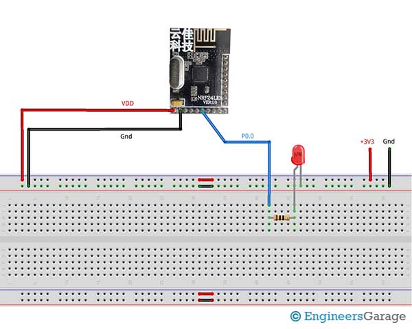
Fig. 1: Prototype of NRF24LE1 Module based LED Blinking
The NRF24LE1 comes in 24-pin, 32-pin and 48-pin package. We will be using 32-pin package. This package contains 15 I/0(input/output) pins. These 15 pins are also used for UART, I2C, PWM, and ADC. The remaining 17 pins are already used for antenna, crystal oscillator, VCC, ground and programming.
We have options to define these pins as input or output and also analog or digital. For this we have different registers by which we can do this.
For choosing between input and output direction, we have PnDIR register where n is the number of port. By this register we can change the individual pin direction. In this register 1 refers to input and 0 refers to output. For example, P0DIR = 0x00 means all pins of Port0 are set as output. Another example, P1DIR = 0x01 means pin0 of Port1 is input and other are output.

Fig. 2: Image of NRF24LE1 Module based LED Blinking
For choosing between analog and digital, we have PnCON register. By default, all pins are set as digital pins. For now, we will leave the discussion of PnCON register as it is complex. You may refer datasheet for more details. For LED blinking we will use P0.0 i.e. pin0 of Port0.
Now after declaring pins as digital output, we have to change the output voltage at this pin. This can be done by assigning 1 or 0 to Pnm, where n is port number and m is pin number. For example, P01 = 1 which means P0.1 is set as high. The code has been mentioned for a greater understanding. Stay tuned for our more articles.
Project Source Code
###
//Program to#include "reg24le1.h" // I/O header file for NRF24LE1#include "hal_delay.h" // header file containing delay functions// main codevoid main(){P0DIR = 0x00; // set PORT0 as outputwhile(1) // infinite loop{P00 = 0; // make Pin0 of Port0 lowdelay_ms(1000); // delay of 1 secondP00 = 1; // make Pin0 of Port0 Highdelay_ms(1000); // delay of 1 second}}###
Circuit Diagrams
Project Video
Filed Under: Electronic Projects
Filed Under: Electronic Projects

Questions related to this article?
👉Ask and discuss on EDAboard.com and Electro-Tech-Online.com forums.
Tell Us What You Think!!
You must be logged in to post a comment.