Trigger pulse generation using mechanical switches like reed switch… etc.., is difficult and critical. Presented here is the circuit that generates single trigger pulse when a step positive voltage is applied.
CIRCUIT AND WORKING
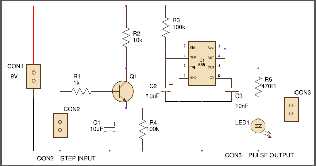
The circuit is built around popular 555 timer, BC547 NPN transistor, and few other components. The 555 timer was configured as a monostable mode to generate a single pulse. The monostable generates a pulse when a negative trigger applied at pin 2. If the width of the trigger pulse is greater than the output pulse of 555, the timer re-triggers itself and generates one more pulse. This creates a pulse train when step voltage is applied as a trigger at pin 2. This problem is avoided by the one-time trigger network components Q1, R4, and C1.
When a step positive (HIGH) voltage is applied at CON2, the capacitor C1 conducts initially and pulls the emitter pin of transistor T1 to ground thereby it saturates T1. Thus the pin 2 receives negative trigger and the timer generates a pulse. The resistor R1 limits the base current of transistor Q1. The resistor R2 is a pull-up resistor that helps to stay the pin 2 in the HIGH state. After the capacitor is fully charged, the transistor goes cut-off thereby it doesn’t allow to re-trigger because the pin 2 is held HIGH by the pull-up resistor R2. The resistor R4 act as a discharge path for capacitor C1 when the step voltage was removed. The width of the output pulse is calculated by the formula,
Time period (in seconds), T = 1.1*R3*C2
The circuit gives a pulse width of about 1.1 seconds. The output pulse is indicated by the LED. The width of the pulse can be varied by changing the value of R3 and C2 by using the above formula. Any external circuit can be connected to the CON3 to trigger it.

Fig. 1: Signal Diagram of Input and Output of Level to Pulse Converter
CONSTRUCTION AND TESTING
An actual size single side PCB can be used for the circuit. The circuit can be powered by 9V battery or any 9V DC Source. A momentary pushbutton can be connected across pin 2 to ground for manual triggering.
Circuit Diagrams
Filed Under: Electronic Projects

Questions related to this article?
👉Ask and discuss on Electro-Tech-Online.com and EDAboard.com forums.
Tell Us What You Think!!
You must be logged in to post a comment.