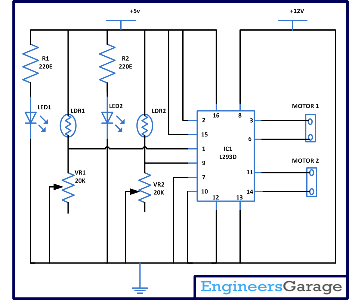
This circuit describe a simple line following robot which a you can easily make in your homes because it does not contains any complex digital circuitry and this can be made without using any microcontroller. In this circuit the robot the will follow a white line on black surface. This simple circuit is made with the help of single IC that is L293D and few more commonly known components.
[[wysiwyg_imageupload:11363:]]
Fig. 1: Prototype of Line Following Robot Circuit on Breadboard
In this circuit we are using L293D IC as a motor diver IC to control the movements of motors and we are using LDR’s as a sensor which will sense the path for the robot to follow. Before understanding the working lets understand the working of individual components.
1.LDR which is working as a sensor here. LDR is basically made up of semiconductor material. Semiconductor material has energy band where electrons and holes exist. These are present on valence band and the conduction band. For conduction to take place electrons must exist in conduction band. Bur energy gap prevents the electrons from moving into conduction band. Therefore electrons need energy to reach to conduction band. And this energy is provided in the form of electrical energy by connecting a power supply to the semiconductor material. The number of electrons present in the conduction band and energy gap will give you the resistance of the material. Similar phenomenon happen in LDR when light fall on LDR, Due to light energy electrons move to conduction band causing resistance to decrease.
In short LDR can be define as- LDR is a device whose sensitivity depends upon the intensity of light falling on it. The resistance of LDR decreases when intensity of light falling on it increases and vice versa (resistance increases when intensity of light falling on it decreases). In dark or in absence of light, LDR exhibits a resistance in the range of mega ohms, which decreases to few hundred ohms in presence of bright light.
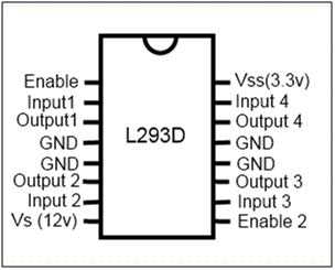
2. L293D– It is a motor driver IC which is used to drive the motor on either direction. L293D comes in 16 pin dual inline package. And can drive two sets of DC motor with the help of single IC which can be move independently according to the input provided. It works on the theory of H bridge which permit voltage to flow in either direction in clockwise or anti clockwise direction. Pin diagram of L293D is as follows-

Fig. 2: Pin Diagram of L293D
From the pin diagram you can see that it has two enable pin that is pin 1 and pin 9. For rotating the DC motor enable pin should be high. For example if you want to rotate the left motor than enable pin 1 should be high. Similarly for right motor pin 9 should be high. And if any of the pin is low than that motor will not work and if both the pins are low robot will stop moving.
L293D contain four input pin 2 pin for controlling each motor. Like pin 2 and pin 7 are on left side and control the rotation of the left motor and pin 15 and pin 10 are on right side and they control the rotation of right motor. And there outputs pin are pin 3 and 6 for left motor and pin 11 and pin 14 for right motor. Following table shown below will help to you know in which direction motor will rotate when logic 0 and logic 1 is provided on the pins.
|
Pin 2 |
Pin 7 |
Motor Rotation |
|
Logic 1 |
Logic 0 |
Clockwise Direction |
|
Logic 0 |
Logic 1 |
Anticlockwise Direction |
|
Logic 0 |
Logic 0 |
No rotation |
|
Logic 1 |
Logic 1 |
No rotation |
3. LED stands for light emitting diode. It is made up of semiconductor device which emit different light source as its output. LED is a semiconductor diode that emits narrow-spectrum light when electrically biased in the forward direction of the p-n junction. When LED is switch on in this electronics combines with hole and the device release energy in the form of light.
4. Motors – You can use two 200rpm DC motors and it should be connected with wheel for moving the robot. in place of motor I have used LED.
Working of circuit is very simple consider two cases-
1. Case 1 when sensor is placed on black line – As we know in dark LDR has very high resistance in the range of M ohms. Now if we want to calculate the voltage at this point. Suppose resistance of LDR is 1M ohms.
Than voltage at this point is –
= 5*20*1000/((20*1000)+(1*1000000) V
= approx 0V
2. Case 2 when sensor is placed on white line- At this time light fall on LDR and its resistance is very low. Suppose it may be 1 or 2 ohms.
Then voltage at this point is-
= 5*1*1000000/((20*1000)+(1*1000000))
= approx 5V
So from the above calculation it is clear that when robot is on black line it will give you logic 0 and when it on white line it will give you logic 1. And from the circuit diagram you can see that this pin is connected to enable pin of L293D IC pin number 1 and 9 and from above it is clear that when this pins are high then only motors will rotate according to the table show below.
While soldering the sensor (LED + LDR) make sure there wire will long enough because they have to look at the line which robot will flow else it will create a problem in following a path. And cover the LDR and LED properly and pair them together -so that light of the room will not affect its working.
Circuit Diagrams
Project Components
Project Video
Filed Under: Electronic Projects
Filed Under: Electronic Projects


Questions related to this article?
👉Ask and discuss on EDAboard.com and Electro-Tech-Online.com forums.
Tell Us What You Think!!
You must be logged in to post a comment.