Day-in and day-out we have been using electronic scales or weighing machines. You go to any grocery store or a jewellery shop; the items are weighed using electronic weighing machines (Weighing balances are also used in situations where very high accuracy is not of paramount importance). But, have we ever given a thought on the mechanism of the electronic scales?
At the heart of electronic scales or weighing machines is a sensor called load cell. These sensors sense the force (or weight) of the items and the electronic circuitry processes the sensors’ output and displays it on the indicator. Load cells are highly accurate transducers which provide the user with information not generally obtainable by other technology due to commercial factors. 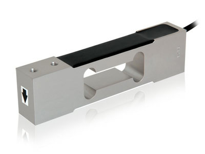

Fig. 1: A Representational Image of a Load Cell
Usage of load cell is not limited to electronics scales; they are used load testing machines, industrial scales, flow-meters, etc., though we hardly ever come in direct contact with the load cells. In short, load cell can be used wherever there is a requirement of “force measurement”.
Subsequent sections will discuss in-outs of the load cells.
What is Load Cell
As per dictionary, a load cell is described as a “weight measurement device necessary for electronic scales that display weights in digits.” However, load cell is not restricted to weight measurement in electronic scales.
Load cell is a passive transducer or sensor which converts applied force into electrical signals. They are also referred to as “Load transducers”.
Load cells use different operating principles, viz.,
· Load Cells based on fluid pressure
· Load Cells based on elasticity
· Load Cells based on magnetostriction effect or piezoelectric effect
However, the only load cells which are prevalent are the load cells based on strain gages. Hence, the term ‘load cell’ means ‘strain gage-based load cells’. The reason behind the wide adoption of strain gage-based load cells is their characteristics
1. Highly precise and linear measurements
2. Little influence due to temperature changes.
3. Small size compared with other types of load cells.
4. Long operating life due to lack of moving parts or any parts that generate friction.
5. Ease in production due to small number of components.
6. Excellent fatigue characteristics
Measurement Principle
MEASURMENT PRINICIPLE
Load cell primarily consists of a spring material and strain gage. Spring material causes strain due to applied load and strain gage changes its resistance in accordance with the change in strain.
1. Spring Material
The sensing or spring element is the main structural component of the load cell. The element is designed in such a way that it develops a strain, directly proportional to the load applied.
When external force is applied, a molecular force works between the molecules constituting the object, generating an internal force that tries to prevent the deformation by the applied force. When the external force is balanced with the internal force generated inside the object, the deformation of the object ceases. At this moment, the internal force per unit area that is generated on the cross section of the object is called the “stress” and the change in dimensions per unit original dimensions is called “strain”. The spring material develops the strain in proportion to applied force.
In order to enhance the performance of a load cell, the characteristics of the spring material are very important.
· Creep, the phenomenon that occurs when the deformation of an object caused by external force becomes larger with time, should be small.
· The material should have a high proportional limit, which guarantees a wide range of linearity.
· Secular variation, change in an object due to permanent stress with passage of time, should be small
· The resistance to impact should be high.
· It should have good workability.
Nickel-chrome-molybdenum steel, stainless steel, and aluminium steel are some of the materials meeting these requirements.
2. Strain Gage
Strain gages utilise the principle of change in resistance of many metals when they are elongated or contracted. 

Fig. 2: A Diagram of Strain Gauge
Since resistance depends upon the resistivity, length and cross sectional area of the material, the same metallic wire will have different electrical resistance depending on whether it is elongated or contracted. The longer the metallic string becomes, the larger the resistance. The strain gauge utilizes this principle and is defined as a device whose electrical resistance varies in proportion to the amount of strain in the device.
The metallic strain gauge consists of a very fine wire or, more commonly, metallic foil arranged in a grid pattern. The grid pattern maximizes the amount of metallic wire or foil subject to strain in the parallel direction. The cross sectional area of the grid is minimized to reduce the effect of shear strain and Poisson Strain. The grid is bonded to a thin backing, called the carrier, which is attached directly to the test specimen. Therefore, the strain experienced by the test specimen is transferred directly to the strain gauge, which responds with a linear change in electrical resistance. Strain gauges are available commercially with nominal resistance values from 30 to 3000 ?, with 120, 350, and 1000 ? being the most common values.
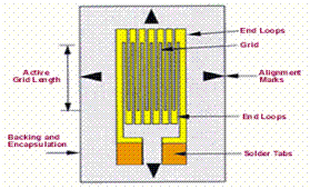
Fig. 3: A Figure Representing Grid of a Metallic Strain Gauge
A load cell is made by bonding strain gauges to a spring material. To efficiently detect the strain, strain gauges are bonded to the position on the spring material where the strain is maximum. When the stress caused by applied force to an object is below the proportional limit, the strain varies linearly with the stress and the resistance value of the strain gauge varies linearly with the deformation.
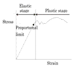
Fig. 4: A Diagram Showing the Linear Relationship Between Stress and Strain Gauge
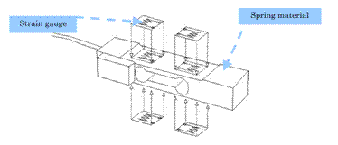
Fig. 5: A Figure Illustrating Relation of the Change of Strain Gauge in Context to Spring Material
Relation of the change in strain to the change in resistance is governed by the Gage factor, defined as the ratio of change in resistance per unit resistance to the change in length per unit length of the strain gage. Therefore,
Change in gage resistance = Gage Resistance * Gage Factor * Strain.
Gage factor of metallic strain gages is approx. 1.5 – 2.
Bonding of strain gages
For strain gage bonding, the adhesive needs to accurately transmit the strain of the spring material to the gage. Desirable properties of the adhesive for strain gage bonding are
· The adhesive bond should have enough strength to withstand temperature and humidity changes
· The bonding should have sufficient insulation against temperature and humidity.
· The degree of shrinkage should be small when curing.
Adhesives used for bonding strain gages are
1. Solvent-vaporization adhesives (such as K-4): These harden at room temperature, and paper gauges, porous base gauges, etc. can easily be attached.
2. Contact-curing adhesives( Alpha-cyanoacrylate adhesives such as CY-10 and Eastman 910 which bonds in a few minutes)
3. Epoxy adhesives
4. Phenol adhesives(Phenol “Bakelite” adhesive requires relatively high adhesive pressure and a long curing time)
Classification
CLASSIFICATION: BASED ON SHAPES OF SPRING MATERIAL
Five commonly used load cell shapes are

Fig. 6: A Figure Representing Column Type Load Cell
1. Column Type
It uses a simple structure and uses 2 strain gages; one in longitudinal and other in transverse direction. It can be used for both tension and compression measurements.
2. Roberval Type (Double-beam Type, Parallel-beam Type)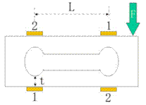

Fig. 7: A Figure Representing Parallel Beam Type or Roberval Type Load Cell
These load cells use bending as the sensing principle. When a force (F) is applied to the Roberval-type load cell, strain gauge 1 contracts while the strain gauge 2 stretches. Value of strain depends upon L, t and width of the beam.
This structure is suitable for high-precision load cells. Bending beams offer high strain levels at relatively low forces, which make them ideal for low capacity load cells. Typical measurement range is generally between 1kg and 1 T, and are not suitable for large capacities
3. Shear Type 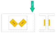

Fig. 8: A Figure Representing Shear Type Load Cell
Strain gauges are bonded at a 45o angle on the neutral axis of the load cell. Shear-type load cells can be made smaller than Roberval-type load cells with the same capacity. They are strongly resistant to transverse loading and it is easy to make them highly precise. The measurement range is generally between 100kg and 20 T.

Fig. 9: A Figure Representing Annular or Ring Type Load Cell
4. Ring Type (Annular Type)
The ring load cell is a high precision load cell and primarily has an intermediate capacity, ranging from 500kg to 20ton.
5. Diaphragm Type

Fig. 10: A Figure Representing Diaphragm Type Load Cell
The diaphragm-type load cell has a round shape. The primary advantage of using a diaphragm-type load cell is that its height can be lowered and it is resistant to transverse loading.
CLASSIFICATION: BASED ON DIRECTION OF LOADING
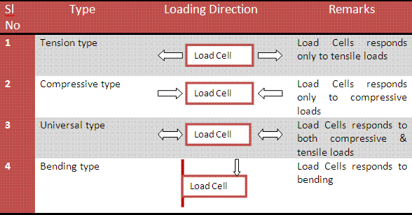
Fig. 11: A Table Representing Different Types of Load Cell on the Basis of Direction of Loading
CLASSIFICATION: BASED ON OUTER SHAPE
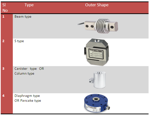
Fig. 12: A Table Representing Different Types of Load Cells Based on the Outer Shape
CLASSIFICATION: BASED ON AIR TIGHTNESS

Fig. 13: A Table Representing Different Types of Load Cells Based on the Air Tightness
Specifications
LOAD CELLS – SPECIFICATIONS
1. Rated Capacity or Rated Load
1. Rated Capacity or Rated Load
Rated capacity is defined as the maximum load that a load cell can measure while meeting its specifications. Upto the rated capacity, the result of measurement should not be affected by an error exceeding the maximum permissible error.
Example: Rated capacity: 100 kg
2. Rated Output
Rated output is the difference when there is no load and when there is a load of rated capacity. It is generally expressed in output per excitation voltage (mV/V); alternatively called “span.”
Example: Rated Output: 1 mV/V
3. Overload, safe
Safe Overload is the maximum load that can be applied without producing a permanent shift in the performance characteristics beyond those specified; specified as a percentage of the
measuring range (i.e. 150% of rated capacity).
4. Compensated Temperature Range
Compensated temperature range is the temperature range within which the rated output and the zero balance are compensated to meet load cell specifications.
5. Zero Balance
Zero balance is the electrical output generated when a rated excitation voltage is applied without any load on the cell. It is generally expressed as a percentage of rated output.
Example: Zero Balance: 10±5% of Rated ouput.
6. Temperature Effect On Zero Balance
Temperature Effect On Zero Balance is the drifting of the zero balance caused by changes in the ambient temperature. This value is expressed as a percentage of rated output.
Example: Temperature effect on zero balance: 0.04% of Rated ouput/10 oC
7. Temperature Effect On Rated Output
Temperature Effect On Rated Output is the drifting of the rated output caused by changes in the ambient temperature.
Example: Temperature effect on span: 0.014% of Load/10 oC Typ.
8. Nonlinearity
Nonlinearity is the maximum deviation in output from a linear calibration curve linking the zero balance and the rated output.
9. Hysteresis Error
Hysteresis error is the maximum difference in output generated when a load increases and decreases.
10. Combined Error
Combined error is the maximum deviation of output from a linear calibration curve linking the zero balance and the rated output, including when a load increases and decreases. It is specified as a percentage of the rated output.
11. Recommended/Maximum Excitation Voltage
The recommended/maximum excitation voltage is the voltage applied to the input terminals of a load cell. Typical excitation is 10 Vdc.
12. Insulation Resistance
Insulation resistance is the direct current resistance between a load cell unit and its circuit.
Example: Insulation resistance: 500 M?/DC 50 V
Configuration
LOAD CELL CONFIGURATIONS
On application of external force, strains generated in the spring material are transformed to resistance change by strain gages. Since the change in resistances is very small, Wheatstone Bridge, a circuit used to detect minor changes in resistance, is used. Wheatstone Bridge is the network of four resistors as shown in figure.
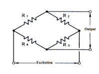
Fig. 14: A Diagram Representing Load Cells Configuration
Depending upon the number of strain gages used in the load cell, load cell is used in following three configurations
1. Quarter Bridge
In this configuration, only one strain gage(out of the four) is used to sense the strains. It forms one arm of the Wheatstone Bridge. Rest three resistances of the bridge are provided in the bridge completion network in the signal conditioning circuit.
2. Half Bridge
In this configuration, two strain gage are bonded in the load cell to sense the strains and these two forms two arms of the strain gage. Rest two resistances of the bridge are completed in the signal conditioning circuit.
3. Full Bridge.
In this configuration, all the four strain gages are bonded in the load cell to sense the strains. This configuration provides maximum sensitivity and is not affected by temperature changes.
Selection of Load Cells
LOAD CELLS – SELECTION
Few things must be taken into account while selecting a load cell for an application.
· Capacity
· Capacity
Apart from the measure load to be measured, initial, impact coefficient, load eccentricity coefficient should be taken into account. Thus capacity of the load cell selected should be higher by minimum of 10% of the maximum load to be measured.
· Dynamic Range
If load cell of very high capacity is selected, it may not be measure very small loads very accurately. As a rule of thumb, loads to be measured should be in the 10% to 90% of the rated capacity of the load cell.
· Shape
Shape of the load cell primarily depends upon the application and mounting arrangements of the load cell. For example, S-type is suitable for applications where force is applied on both the ends, whereas diaphragm type is suitable for applications wherein force is applied only at one end.
Besides this, other specifications like rated output, temperature range, errors, and protection class should be given appropriate attention.
LOAD CELLS – BENEFITS
· Load cells are used in various industries to measure the mass or weight of the products electronically. Electronic data can be used for automated product check.
· Load cells are used in various industries to measure the mass or weight of the products electronically. Electronic data can be used for automated product check.
· Load cells provide quick and precise measurements.
· Compared with other sensors, load cells are relatively more affordable and have a longer life span.
Filed Under: Articles


Questions related to this article?
👉Ask and discuss on EDAboard.com and Electro-Tech-Online.com forums.
Tell Us What You Think!!
You must be logged in to post a comment.