This circuit can indicate the ON / OFF status of AC Loads. Two high bright LEDs indicate the power ON and power OFF status of the load connected to the AC outlet. It is highly useful to avoid the wastage of electricity if devices like heater, electric iron, Soldering iron etc are switched on unnecessarily for long time.
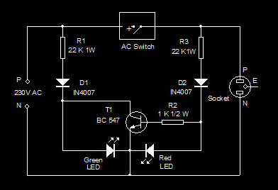
The circuit is directly powered from Mains and can be enclosed in the existing switch board. First part of the circuit is connected before theOn/Off switch and the second part after the switch. Resistor R1 and R2 reduces the AC voltage to a safer level for the semiconductors and Diodes D1 and D2 rectify the reduced AC.

Fig. 1: Circuit diagram of electronic circuit indicating the ON / OFF status of AC Loads
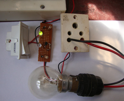
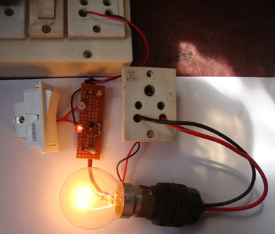
When the switch is in the Off position, diode D1 forward biases and Green LED remains on. This indicates the mains availability as well as the Load Off status. When the switch is in the ON state, D2 forward biases to light the Red LED. At the same time, transistor T1 saturates and drains the anode current of Green LED. This turns off the Green LED.

Fig. 2: Prototype of Load Switched off
BC 547 is used as the switching transistor. It can handle up to 45 volts.

Fig. 3: Prototype of Load Switched On
Note : The circuit can be enclosed in the existing switch board . Always connect the circuit across the load switch after checking the phase and neural lines with a tester. Do not change the polarity. Make sure that the switch is connected in the phase line. As a safety measure, switch off the Mains switch before opening the switch board.Double check the soldering points for any shorting before connecting to AC.
Test Result
The circuit was tested 24 hours and no heating or burning occurred in the transistor and other components.
Caution: This circuit becomes extremely dangerous if handled carelessly. Since it is connected to AC, lethal potential exists in all parts .So do touch any points of the circuit when it is connected to mains. Troubleshoot the circuit only after removing it from the AC. Do not try this circuit, if you are not experienced in handling high voltage.
Filed Under: Electronic Projects


Questions related to this article?
👉Ask and discuss on Electro-Tech-Online.com and EDAboard.com forums.
Tell Us What You Think!!
You must be logged in to post a comment.