Whenever we are testing and troubleshooting any digital circuit the most required handy tool is the logic probe. The logic probe is used to check HIGH or LOW logic. There may be LED or buzzer type of indication for indicating whether logic is HIGH or LOW. Like there may be:
• Simple LED indication – means LED glows if logic is HIGH and vice versa
• different colour LED (RED – GREEN) to indicate HIGH and LOW logic
• buzzer that sounds if logic is HIGH and does not sounds if logic is LOW
But what if the probe has a display that displays ‘H’ for HIGH logic and ‘L’ for LOW logic? Isn’t is nice and sounds interesting? Such circuit can be built with very few and cheap components. The circuit is also very easy to build.
So do you want to build such circuit? Obviously, your answer should be yes. So let’s start. First, see the circuit diagram and then its description and working.

Fig. 1: Prototype of Seven Segment Display based Logic Probe
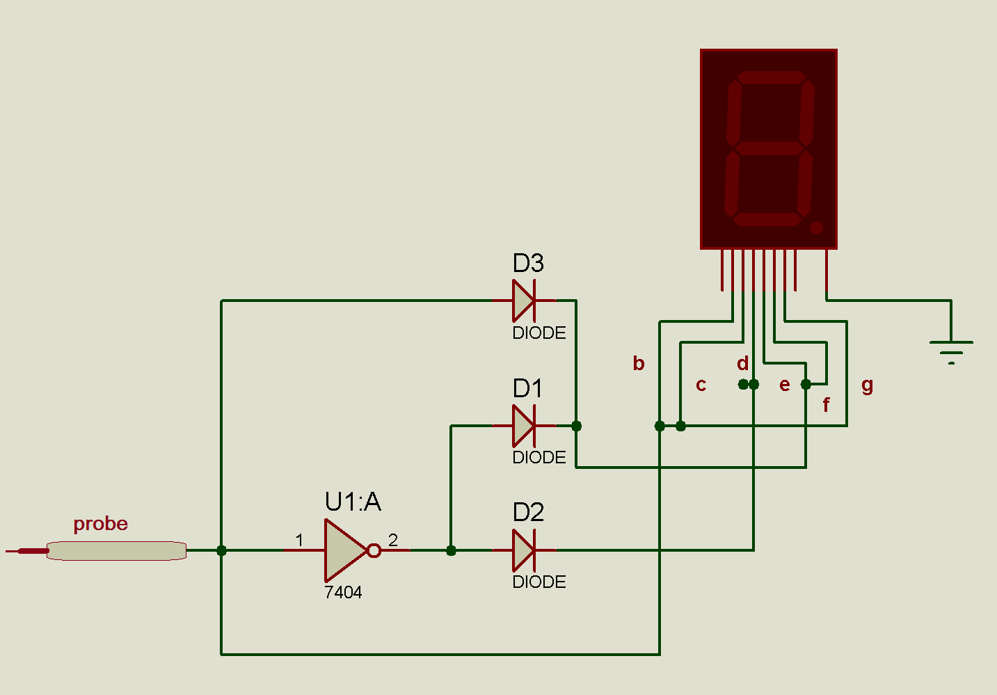
Circuit Diagram:
As I have told, the circuit consists of fewer components and very easy to build. It consists of one INVERTER chip 74LS04, one common cathode type 7-segment display and 3 diodes only.
Circuit Description:
• The common cathode terminal of the display is connected to ground.
• Segment terminals b, c, and g are shorted together and connected to probe directly.
• The probe is also connected to segments e and f but through diode D3.
• The probe is also connected to the input of one INVERTOR and the output of INVERTOR is connected to segment d through diode D2 and to segments e and f through diode D1.
Circuit Operation:
• When the probe is connected to HIGH logic, it will display ‘H’. For this segments, b, c, e, f, and g all will turn ON.
• And when the probe is connected to Low logic, it will display ‘L’. For this only segments d, e and f will turn ON.
• There are three conditions for the probe (1) not connected (2) connected to logic HIGH and (3) connected to logic LOW.
• In the 1st condition when the probe is in floating condition, none of the segment glows.
• When the probe is connected to HIGH logic, immediately segments b, c and g will turn ON and also segments e and f also turn ON because diode D3 is forward bias. Only segment d will turn Off because HIGH logic is inverted by U1A chip and it will turn it OFF. Thus ‘H’ is displayed on 7-segment.
• Now when the probe is connected to LOW logic, segments b, c and g will turn OFF. This LOW logic is inverted to HIGH by U1A. So diodes D1 and D2 will forward bias that will turn ON segments d, e and f. Thus ‘L’ is displayed on 7-segment.
Circuit Diagrams
Project Video
Filed Under: Electronic Projects
Filed Under: Electronic Projects

Questions related to this article?
👉Ask and discuss on EDAboard.com and Electro-Tech-Online.com forums.
Tell Us What You Think!!
You must be logged in to post a comment.