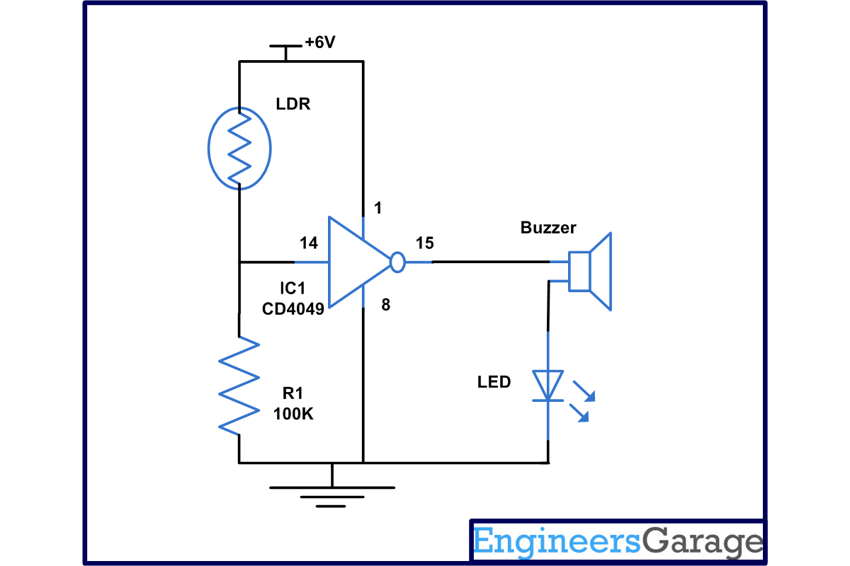
Magic eye can be used as automatic guest indicator in your home. Just install this at the bottom of the door and whenever a person would arrive, his shadow will fall on the circuit giving an indication that somebody is present on the door without the knowledge of the visitor. It can also used as a prevention measure against vandalism. So, apart from homes, it can also be used shop and banks. This circuit is based on popularly known hexa inverter IC CD4011, LDR and a few more components.
The magic eye circuit is based on NOT gate CD4049 IC. In this circuit, we are utilizing only 1 gate of IC. To understand the working you should know about the truth table of NOT gate which is:
INPUT | OUTPUT |
0 | 1 |
1 | 0 |
In NOT gate, we will get output as logic high when logic zero is provided and we will get logic zero when logic1 is provided in input.
CD4049 contain six inverter gates in one package as shown in diagram. In this pin 3 is in and 2 is for output for first gate similarly pin 5 is input and pin 4 is output for second gate similarly we have four more gate. In this 1 is for supply voltage and pin is connected to ground and pin 13 and 16 are unused pin.

Fig. 1: Pin Diagram Of CD4049 IC
Working of this magic eye circuit is very simple as we know LDR has a characteristic that its value of resistance depends on the amount of light falling on it means it shows very high resistance of about 1 Mega ohms in darkness but a resistance of few kilo ohms in light here we utilize this phenomenon to make magic eye.
When light is falling on LDR, its resistance gets very low and as a result input at pin 14 will be high. We will receive logic zero at output pin therefore LED and buzzer connected at output will not sound. But as soon as shadow falls on LDR, its resistance will go high. So, we receive logic high at output means +6volts and the LED and buzzer connected to it start sounding.
It you want that this circuit should work in night also then add a LED in parallel to LDR with a resistor of 1K. You can also connect relay at the output for that connect a resistor of 1K form output and through that connect a transistor may be BC547 than connect your relay.
Circuit Diagrams
Project Components
Filed Under: Electronic Projects


Questions related to this article?
👉Ask and discuss on EDAboard.com and Electro-Tech-Online.com forums.
Tell Us What You Think!!
You must be logged in to post a comment.