A battery charger is a circuit that recharges a battery by resupplying charge carriers (electrons) to it. The charging of the battery depends on the type of the battery. There are many types of batteries using different electrolyte materials. Irrespective of the type, the batteries have a common problem of overcharging and over discharging. Different batteries have different tolerance limit for overcharging. Some batteries are so sensitive that they may explode after a certain limit of charging.
In order to avoid overcharging and consequent damage to the battery, an intelligent charging circuit needs to be designed. This circuitry will be responsible for charging the battery and when the overcharging voltage is reached, it should cut off the charging process. In this project, smart charger for Li-ion batteries is designed. The batteries considered for charging are taken of 3.7 V specification. By modifying the same circuit, battery charger for Li-ion batteries with different supply voltage specifications can be easily designed.
For charging of Li-ion batteries, there are different methods that can be used. These methods are actually the modes of battery charging. Basically, there are three modes of battery charging –
1) Trickle Mode
2) Constant current mode
3) Constant voltage mode
In this experiment, a battery charger for 3.7V Li-ion battery with an output power of 4.2 V / 1 A is designed. To design an intelligent circuitry which can monitor the charging process in real time, an integrated circuit TP4056 is used.
This IC provides sufficient charging current and voltage to a 3.7V Li-ion battery. The IC can automatically cut off the charging current when the battery is fully charged. Therefore, it reduces the risk of permanent damage to the battery.
Components Required

Fig. 1: List of Components required for 3.7 V Li – ion Battery Charger
Circuit Connections
In this electronics project, a 3.7 V Li-ion battery is used to store the charge which is fully charged when its terminal voltage reaches 4.2 V. As any battery charges, the voltage output across its terminals keeps on increasing. Every battery has a peak terminal voltage value for which the battery is fully charged. So, the charging percentage of battery is also estimated by measuring the terminal voltage. The Li-ion battery needs to be handled carefully as the battery may catch fire due to overcharging. Therefore for charging the Li-ion battery, special ICs like TP4056 IC are used which automatically disconnect the battery from input supply as the battery is fully charged.
The TP4056 is a specially designed IC to charge the 3.7 V Li-ion batteries. This is a linear battery charger controller with constant current and constant voltage. By adding a single programmable resistor the IC can be used to charge a 3.7V Li-ion battery. The charge voltage is fixed at 4.2V and charging current can be set by adding some resistor and capacitor according to the battery to be charged. This IC can provide a maximum charging current of 1A.
The IC also provides internal thermal protection, current limitation, and negative charge current. When the battery is fully charged then the TP4056 charger cuts down the current. So there may be a possibility that current flows from the battery to TP4056 IC when the battery is at high potential. Therefore there is no need to add extra blocking diode due to the internal PMOS which blocks the negative charge current. When the battery fully charges the IC cuts off the charging current which saves the battery from any damage.
The TP4056 IC comes in SOP package which makes it ideal for use in portable devices. It also requires less external components, none other than few resistors and capacitors. The IC needs minimum 4 V to 8 V voltage for its operation. The IC has 8 pins with the following pin configuration –
| Pin | Name | Function | Description |
|---|---|---|---|
| 1 | TEMP | Temperature Sense Input | If TEMP pin’s voltage is below 45% or above 80% of supply voltage VIN for more than 0.15 Seconds, this means that battery’s temperature is too high or too low, so the charging is suspended. The temperature sense function can be disabled by grounding the TEMP pin. |
| 2 | PROG | Constant Charge Current and Charge Current Monitor Pin | The pin is set by connecting a resistor RISET from this pin to GND. The voltage on ISET pin can be used to measure the charge current. |
| 3 | GND | Ground Terminal | Ground |
| 4 | VCC | Positive Input Supply Voltage | When Input Voltage drops to within 30 mv of the BAT pin voltage, TP4056 enters low power sleep mode, dropping BAT pin’s current to less than 2 uA. |
| 5 | BAT | Battery Connection Pin | It must be connected to positive terminal of the battery. BAT pin provides charge current to the battery and provides regulation voltage of 4.2 V. |
| 6 | STDBY | Open Drain Charge Status Output |
On battery charge termination, this pin is pulled low by an internal switch, otherwise is in high impedance state.
|
| 7 | CHRG | Open Drain Charge Status Output | When the battery is being charged, this pin is pulled low by an internal switch, otherwise is in high impedance state. |
| 8 | CE | Chip Enable Input |
A high input at this pin will put the device in the normal operating mode otherwise put the IC in disable mode.
|
The TP4056 IC has Automatic recharge feature. When the battery voltage drops down to approximately 4.05V then the IC will again start its charge cycle. This will again restart the charging of the battery. It comes with temperature sense. Its pin 1 or TEMP pin is connected to the NTC (negative temperature coefficient) thermistor output which is inbuild in the battery pack. If the pin voltage is below 45% or above 80% of supply voltage for more than 0.15s which means the battery temperature is very high or very low then it stops the charging of the battery. Grounding this pin disables the function of temperature sense pin. In this experiment, this pin will be grounded which will disable the functionality of temperature sense pin.
For charging the 3.7V Li-ion battery, TP4056 module readily available in the market can also be used. This module provides all the components embedded with TP4056 IC and it is specially designed for charging single 3.7V Li-ion battery. For complete understanding of the charger circuit, it is designed from scratch in this project.
The TP4056 IC has the following pin diagram –

Fig. 2: Pin diagram of TP4056 IC
First of all the IC needs to be provided input supply which will then provide power to the battery being charged. The following pins on the IC are designed to connect with the external power source –
Gnd(pin 3) – It provides ground to the IC and needs to be connected to the negative terminal of the battery.
Vcc(pin 4) – This is the Input supply pin.
So, provide input supply to the IC. When the supply voltage drops to within 30mV of the BAT pin voltage. Then TP4056 goes into sleep mode and reduces the current supplied to the BAT pin to less than 2uA. The BAT pin is that, at which positive terminal of the battery is to be connected. The IC input voltage must be from 4V to 8V voltage for its normal operation.
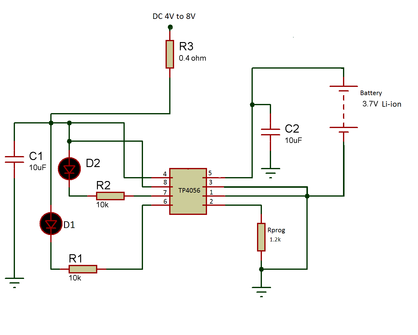
In this experiment, a 5V supply to the IC is provided. A capacitor is also connected from Vcc to ground for bypassing unwanted voltage spikes and noise. However the large value of capacitor need to decouple with a series resistor(shown as resistor R3 in the circuit diagram) of 0.2 ohms to 0.5 ohms which reduces the ripple voltage.
Secondly, the TP4056 IC needs to be enabled. For this CE (pin 8) – Chip enable is provided. A high input at this pin enables the TP4056 IC and pulling this pin low disable the IC. So, this pin has been directly connected to the supply voltage to enable the IC.
Now, the charging current has to be set according to the battery used. For this purpose, Prog (pin 2) is provided. This pin decides the battery charging current by using a programmable resistor(RPROG) connected from the pin to the ground. This pin provides a constant reference voltage of 1V (VPROG) for an external resistor connected between this pin and ground.
The voltage in constant current mode is regulated at 2V and in precharge mode at 0.2V at this pin. In constant current mode, the charging current is 1200 times the current through this resistor. In both the mode(constant current and precharge mode ) the voltage is used to measure the current at this pin by the following equation:
Current at PROG pin, Iprog = ( VPROG/RPROG )
The charging current of the battery can be calculated as follows –
Icharge = Iprog *1200
In this experiment, 1A of charging current(Icharge) will be set to charge the battery. For 1A current, resistor Rprog is connected with this pin to the ground(as shown in the circuit diagram). The value of resistor Rprog can be calculated as follows –
Icharge = Iprog *1200 (as exapined above)
Icharge = (Vprog/ RPROG)*1200 (from above equation of Iprog )
RPROG = (Vprog/ Ibat)* 1200 (Icharge =1A and VPROG = 1V)
Rprog = (1/1)*1200
Rprog = 1.2k

Fig. 3: Circuit Diagram showing Programmable Resistor to set Charging Current
Now the battery can be connected to the TP4056 IC. For connecting the battery, BAT(pin 5) or Battery connection pin is provided. The positive terminal of the battery is connected to this pin. This BAT pin provides the regulated 4.2V and charging current to the battery. In this experiment, a capacitor is connected in parallel with the BAT pin which connects to the ground for bypassing unwanted voltage spikes and noise(as shown in figure below) –

Fig. 4: Circuit Diagram showing battery connection with TP4056 IC
For the visual indication of the charging of the battery, the CHRG (pin 7) or Charging status of battery pin can be used. When the battery is charging then this pin goes low otherwise, it remains in high impedance state. For the visual indication of battery charging, a Red LED is connected with a resistance (R2) in series to this pin which will lights up when the battery is charging, otherwise it stays in off state. The resistance limits the flow of current from the LED.
For visual indication of full charging of the battery, STDBY (pin 6) or Charge termination status pin can be used. When the battery is fully charged this pin goes low otherwise, it stays in high impedance state.
In this experiment, for the visual indication, a green LED is connected with a resistance (R1) in series at this pin. This LED will lights up when the battery is fully charged otherwise stays in off state. The resistance limits the flow of current from the LED.

Fig. 5: Circuit Diagram showing Charging and Charge Completion Indicating LEDs connection to TP4056
So, this IC requires less number of external components. It has automatic cut off feature when the battery is fully charged. It has Internal overvoltage and thermal protection. The IC provides automatic recharge and fully charge and charging indicator for the battery can be connected to it.
It is important that capacitors should be used at input supply as well as with battery for filtering the signal. This will reduce the unwanted voltage spikes which protect the battery as well as the IC from damage. A resistor (R3 in the circuit diagram) should be connected in series with the large value of capacitor at the input supply to keep the ripple voltage low. The battery should be connected as per polarity indicated on the IC because the IC does not have any reverse polarity protection circuit.
The battery should not be discharged by connecting a load, during the charging process. Simultaneous charging and discharging can reduce the battery life and can harm TP4056 IC. The Input supply must be provided to the IC in its working range. Also, the connections polarity should be correct. While connecting the battery to the TP4056 IC if both red and green LED lights up then the circuit connection of the battery must be checked.
How the circuit works –
During charging of the battery, there are three basic modes in which TP4056 IC operates. There are additional modes as per the embedded features in the IC. These modes can be observed from the following graph taken from the datasheet –
")
Fig. 6: Graph showing Charging Modes of TP-4056 IC (Source – TP4056 datasheet)
1) Trickle mode-
When the battery voltage is less than 2.8V then the IC will enter in trickle charge mode to bring the voltage of the battery in safe mode. In this mode, the charging current (value of current by which battery will be charged) reduces to 13% (Typ 130mA) of the full-scale current. When the battery voltage reaches above trickle voltage (Vtrickle(2.9V) + Delta Vtrickle (0.08V)), the IC enters in constant current mode. In this experiment, the charging current is 1A (as set by the programmable resistor at pin 2). In trickle mode, the charging current will drop down and can be calculated as follows
Itrickle = 13% of Icharge (charging current)
In our case charging current, Icharge = 1A
Itrickle = (13*1)/100
Itrickle = 130mA
2) Constant current mode-
The current flowing out of the PROG pin will be constant. This current is used to charge the battery and is called charging current. In this experiment, this charging current is 1A (Icharge) (as set by the programmable resistor at pin 2) and the battery will be charged through this constant current of 1A until the terminal voltage of the battery will reach its maximum rated voltage (4.2 V).
3) Constant voltage mode-
Now when the battery voltage has reached peak value of 4.2 V then the battery voltage tries to exceed the 4.2 V. Then, the IC will not allow more current to flow through the battery. The current in this mode will slowly start dropping down by maintaining a constant voltage of 4.2 V at the battery (as seen in the above graph).
4) Standby mode-
The IC automatically stops the charging when the charge current drops to 1/10Th of the programmed current/charging current after the maximum voltage (4.2 V) of the battery is reached. In this experiment, this current value can be calculated as follows
I =1/10* (Icharge )Charging current
I = 1/10*(1) (since Icharge = 1A)
I = 0.1A
In this mode, the IC will draw maximum 100uA current as per the datasheet.
5) Shut down mode-
When the RPROG Pin is not connected and the input voltage is less than battery voltage then the IC will be in shutdown mode.
Testing –

Fig. 7: Image of TP-4056 Module and Battery
The input supply provided to the IC is 5V DC so, Vin = 5V
The maximum current provided by the TP4056, Imax = 1A
The charging current for the battery, Icharge is 1A (as set by the programmable resistor connected at pin 2 of the IC). A 3.7 V Li-ion battery having 3000 mAH capacity is being charged by the circuit. Before connecting the battery to the TP4056, the initial battery voltage Vbat measured was 3.98V. When the battery is connected to the TP4056 then current drawn by the battery Ibat was 90mA. The time taken to fully charge the battery was around 5 hours. It should be noted that this charger is designed only for Li-Ion 3.7 V battery.
Circuit Diagrams
Filed Under: Electronic Projects

Questions related to this article?
👉Ask and discuss on Electro-Tech-Online.com and EDAboard.com forums.
Tell Us What You Think!!
You must be logged in to post a comment.