Engineers Garage

  • Projects and Tutorials
    • Electronic Projects
      • 8051
      • Arduino
      • ARM
      • AVR
      • PIC
      • Raspberry pi
      • STM32
    • Tutorials
    • Circuit Design
    • Project Videos
    • Components
  • Articles
    • Tech Articles
    • Insight
    • Invention Stories
    • How to
    • What Is
  • News
    • Electronic Products News
    • DIY Reviews
    • Guest Post
  • Forums
    • EDABoard.com
    • Electro-Tech-Online
    • EG Forum Archive
  • Digi-Key Store
    • Cables, Wires
    • Connectors, Interconnect
    • Discrete
    • Electromechanical
    • Embedded Computers
    • Enclosures, Hardware, Office
    • Integrated Circuits (ICs)
    • Isolators
    • LED/Optoelectronics
    • Passive
    • Power, Circuit Protection
    • Programmers
    • RF, Wireless
    • Semiconductors
    • Sensors, Transducers
    • Test Products
    • Tools
  • EE Resources
    • DesignFast
    • LEAP Awards
    • Oscilloscope Product Finder
    • White Papers
    • Webinars
  • EE Learning Center
    • Design Guides
      • WiFi & the IOT Design Guide
      • Microcontrollers Design Guide
      • State of the Art Inductors Design Guide
  • Women in Engineering

Make a Battery Level Indicator using LM339 IC (Part 7/9)

By Hai Prasaath K

This era is an era of portable devices. Like smartphones and tablets are small computers that can be taken anywhere, more and more gadgets that can be taken anywhere are the new craze. These light-weight and portable devices are being developed in domains of electronic applications. All such devices are run on batteries. The batteries are the lifeline of all such devices. The use of batteries itself though requires certain precautions. The most common issue with the use of batteries is their overcharging and over discharging. Also, it is important to keep track of the charge level of batteries attached to a device, so that it can be timely charged before it discharges to the level that the device gets nonoperational. For the same purpose, the devices that run on batteries must have a battery charge indicator. 
 
Secondly, some batteries have high tolerance limit for overcharging and some may explode after a certain limit of charging. That is why it is important to disconnect the battery from charging when it reaches its maximum limit. A battery level indicator gives the visual indication of the battery state and so allow disconnecting it before over charging. Also, by battery level indicator, the user is instigated to charge the battery before it dies. 
 
Depending upon the state of battery there are two ways to indicate charge level, one is the state of charge (SOC) method and another is the death of discharge (DOD) method. SOC is the measure of the stored charge in the battery and DOD is the measure of the degree by which battery is getting emptied relative to the total capacity of the battery. 
 
In this project, a battery level indicator is designed using state of charge method. SOC method is more convenient to use and easy to design. SOC of the battery can be determined by the voltage level at the terminals of the battery or by measuring current output of the battery. In this project, the SOC of a battery is determined by sensing the terminal voltage level of the battery. Therefore, for sensing the voltage level of the battery, an integrated circuit is required which can precisely detect the voltage across the terminals of the battery.
 
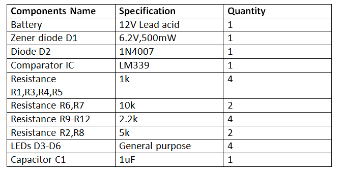
In this project, a 12V Lead Acid battery is used. with a voltage rating of 12 V, this battery has maximum charging voltage at 13.5 V and end of discharge voltage at 10.5 V. The end of discharge voltage is the voltage below which any device connected to the battery will stop operating. For sensing the terminal voltage level of the battery series, LM339 IC is used. 
 
LM339 is a single supply quad comparator which has four channels to detect the magnitude of analog voltages and indicate the voltage level by lighting up to 4 LEDs. So, the IC is designed to indicate four voltage levels respective to a common voltage reference. For voltage indication, LEDs can be connected to the IC. Each LED draws current in the range from 5 mA to 6 mA current. Practically, it is seen that LEDs indicated the voltage level from 10.45V to 13.5V. 
 
sdfszdfsdsdfvdzx

Circuit Connections – 

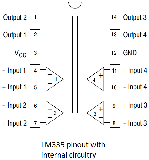
For designing this battery level indicator it is important to understand pin diagram and pin configuration of LM339 IC. This is a comparator IC which is specially designed for low-level sensing. Internally LM339 consists of four OPAM which acts like comparators and detect the voltage level. This IC has low offset voltage (+/- 2 mV) and low bias current (Typically 25 nA). The supply voltage of LM339 can vary from 3V to 36V and split supply can vary from +/-1.5 V to +/-18 V. The input common mode voltage is around -0.3 V to Vcc. The input common mode voltage is the acceptable input voltage range for the operation of LM339.
 
Ideally, the zero-volt output of OPAM should be zero. But due to a mismatch in the input transistor of OPAM, the OPAM gives zero output at non-zero input values. So, an input offset voltage is needed. This voltage is the required voltage at both the input terminals of the OPAM to make the output voltage zero.
 
Bias current or input bias current is the leakage current which flows in and out of the input terminal of the OPAM. The range of input bias current is from Nanoamperes to picoamperes. So, MOSFET OPAM has input bias current in picoampere and BJT OPAM has input bias current in nanoampere. 


Project Source Code


Circuit Diagrams

LM-339-Internal-Circuit


Filed Under: Electronic Projects


Questions related to this article?
👉Ask and discuss on Electro-Tech-Online.com and EDAboard.com forums.


Tell Us What You Think!! Cancel reply

You must be logged in to post a comment.

HAVE A QUESTION?

Have a technical question about an article or other engineering questions? Check out our engineering forums EDABoard.com and Electro-Tech-Online.com where you can get those questions asked and answered by your peers!


Featured Tutorials

  • Introduction to Brain Waves & its Types (Part 1/13)
  • Understanding NeuroSky EEG Chip in Detail (Part 2/13)
  • Performing Experiments with Brainwaves (Part 3/13)
  • Amplification of EEG Signal and Interfacing with Arduino (Part 4/13)
  • Controlling Led brightness using Meditation and attention level (Part 5/13)
  • Control Motor’s Speed using Meditation and Attention Level of Brain (Part 6/13)

Stay Up To Date

Newsletter Signup

Sign up and receive our weekly newsletter for latest Tech articles, Electronics Projects, Tutorial series and other insightful tech content.

EE Training Center Classrooms

EE Classrooms

Recent Articles

  • What is a loop calibrator? 
  • What are the battery-selection criteria for low-power design?
  • Key factors to optimize power consumption in an embedded device
  • EdgeLock A5000 Secure Authenticator
  • How to interface a DS18B20 temperature sensor with MicroPython’s Onewire driver

Most Popular

5G 555 timer circuit 8051 ai Arduino atmega16 automotive avr bluetooth dc motor display Electronic Part Electronic Parts Fujitsu ic infineontechnologies integratedcircuit Intel IoT ir lcd led maximintegratedproducts microchip microchiptechnology Microchip Technology microcontroller microcontrollers mosfet motor powermanagement Raspberry Pi remote renesaselectronics renesaselectronicscorporation Research samsung semiconductor sensor software STMicroelectronics switch Technology vishayintertechnology wireless

RSS EDABOARD.com Discussions

  • What was before microcontrollers ?
  • Measure AC current accurateley (100mA to 10A)
  • 74HC595 creating Fake output
  • NEED HELP FOR OP-AMP IN BGR
  • Check undesired substrate mode...

RSS Electro-Tech-Online.com Discussions

  • Control Bare LCD With ATmega328p
  • Need a ducted soldering fan for solder smoke extraction
  • Sla ir li ion
  • Question about ultrasonic mist maker
  • Best way to reduce voltage in higher wattage system?
Engineers Garage
  • Analog IC TIps
  • Connector Tips
  • DesignFast
  • EDABoard Forums
  • EE World Online
  • Electro-Tech-Online Forums
  • Microcontroller Tips
  • Power Electronic Tips
  • Sensor Tips
  • Test and Measurement Tips
  • 5G Technology World
  • About Us
  • Contact Us
  • Advertise

Copyright © 2022 WTWH Media LLC. All Rights Reserved. The material on this site may not be reproduced, distributed, transmitted, cached or otherwise used, except with the prior written permission of WTWH Media
Privacy Policy | Advertising | About Us

Search Engineers Garage

  • Projects and Tutorials
    • Electronic Projects
      • 8051
      • Arduino
      • ARM
      • AVR
      • PIC
      • Raspberry pi
      • STM32
    • Tutorials
    • Circuit Design
    • Project Videos
    • Components
  • Articles
    • Tech Articles
    • Insight
    • Invention Stories
    • How to
    • What Is
  • News
    • Electronic Products News
    • DIY Reviews
    • Guest Post
  • Forums
    • EDABoard.com
    • Electro-Tech-Online
    • EG Forum Archive
  • Digi-Key Store
    • Cables, Wires
    • Connectors, Interconnect
    • Discrete
    • Electromechanical
    • Embedded Computers
    • Enclosures, Hardware, Office
    • Integrated Circuits (ICs)
    • Isolators
    • LED/Optoelectronics
    • Passive
    • Power, Circuit Protection
    • Programmers
    • RF, Wireless
    • Semiconductors
    • Sensors, Transducers
    • Test Products
    • Tools
  • EE Resources
    • DesignFast
    • LEAP Awards
    • Oscilloscope Product Finder
    • White Papers
    • Webinars
  • EE Learning Center
    • Design Guides
      • WiFi & the IOT Design Guide
      • Microcontrollers Design Guide
      • State of the Art Inductors Design Guide
  • Women in Engineering