Executing a mathematical equation just by pressing a single compile button seems an easy task. There are plenty of computations behind execution by ALU, compiler, linker, and various other peripherals. The equation is translated and broken into smaller instructions.
Instructions require resources to execute. Resources are memory, registers, adders, multipliers, and shifters, etc. On the other hand, resources also require some physical quantities to operate, such as the clock and power.
Let’s go through which mathematical equation is processed and executed by the processor/microcontroller?
![]()
Take the above as input to the processor.
In the microcontroller case, we break the equation into smaller functions/instructions. Each instruction works independently; only the input is dependent on the previous function. The above case equation can break in to
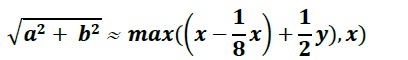
Right and left-hand side equations are nearly equivalent. Right hand side is more flexible and further it can easily be translated in smaller instructions. In above equation x= max(absolute(a), absolute(b)) and y=min(absolute(a), absolute(b)) and ‘a’, ‘b’ are variables
Now equation can be translated into individual instructions and downloaded in microcontroller flash as code for execution.
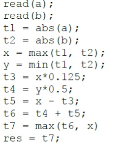
- First, we need to read the variables a and b.
- If the variables are negative, take absolute.
- Populate x= Max among variables and y= Min among variables.
- Create t3, t4, t5, t6, and t7(new variables) and populate each.
Note t3, t4, t5, t6, and t7 are new variables. These variables are necessary, and they hold individual instructions results. The final result is passed to the ‘res’ variable. ‘t7’ holds the final result, but it’s a better practice to pass the result to another variable and free the previous to hold the next result.
Code state machine
An easy way to pictorially view the code is through state machine representation. The whole code is represented in 5 states. Control flow and jump from each state are indicated through arrows. Each possible (error, successful) case is represented in a state machine.
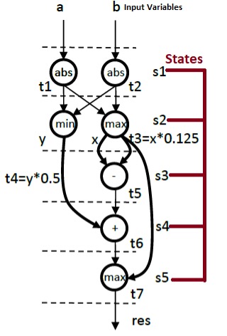
From state machines, multiple information can be extracted, such as latency, resource usage, and it can be analyzed whether resource sharing is possible.
What goes in the Microcontroller?
The microcontroller has many onboard peripherals with memory, core, ALU, multipliers, buses, cache, etc.
These peripherals are known as resources in design terms.
The mathematical equation discussed above also requires resources, and state machines can extract resource usage by a particular application. Let’s extract for equation under discussion.
State1:
For variables, ‘a’ and ‘be two registers are required. Suppose our variables are 1-byte integers. Registers must be 1 byte or greater than 1 byte to assign them our variables. If we assign our variable data greater than the register size compiler will give an error while compiling code.
State2:
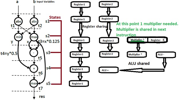
In the second state, three instructions are executed. The first two are finding the minimum and maximum of both the input variables. Both the instructions require two registers. We can share resources and use the previous two registers. Register contents are updated. Now, register1 has a minimum value, and register2 has the maximum value.
Only variable names are changed resource(register) count is the same (resource saved). If we do not share a resource, we should bear the resource cost.
At this stage, we also require one multiplier and another register to save the contents of the multiplication.
State3:
In-state three again resources can be shared 3 registers and 1 multiplier. ALU is also required in this state.
State 3 is the heaviest in all. In total, 3 registers, 1 multiplier, and an ALU is required in this state.
State 4:
In this state, 1 register and ALU are required.
State5:
At last, only 1 register is required to hold the result.
Advantage of resource sharing
In total, five resources are required to execute the above code with resource sharing. Without resource sharing, 16 resources are required. We saved 11 resources. These resources account for cost. Hence, we saved 1/3 of the total cost.
What if we want to build our own processor to execute the above equation?
Well, the processor is a big thing. But we can try to build custom hardware for the above equation. We know from the above information that we need 3 registers, 1 ALU, and 1 multiplier for the above equation execution.
FPGAs are built for this purpose. We can write code for our application. Compile the code, download it in FPGA and test the application. Later on, we can print custom hardware on successful testing.
In our case, we can write code for our equation and analyze the RTL (resistor transistor level) schematic. FPGA HDL (hardware descriptive language) simulators graphically print the RTL schematics. RTL schematic visually shows the circuit inside our design and enlists what resources are required? How much power the system consumes and much more.
We are interested in knowing the resources required. Other parameters are also good to explore.
Let’s jump to HDL code:
I expect that you are familiar with the HDL code or know the structure of code flow.
First, a top-level entity is defined. I named it “squareroot”. This entity is taking clock, reset and start as input, same as microcontrollers. Two variables ‘a’ and ‘b’ as input. The variable length is 1 byte. An output variable named “res”. The output variable length is 9-bits. A ‘ready’ bit indicating the result is ready.
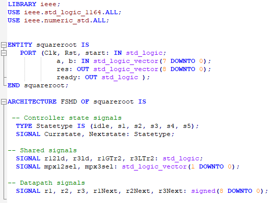
For architecture, recall the state machines again. We defined 5 states s1, s2, s3, s4, and s5. Current and next state variables point to current and next state.
FSM is then divided into data and control paths. Data path executes tasks required to compute data, and control path executes operations for control synchronization.
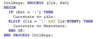
Separate concurrent processes are defined for data and control paths. Another concurrent process is for clock and reset. On reset, control jumps to the idle state, and the state machine starts again. Otherwise, on every positive edge of the clock, jump to the next state.
Through simulation, results can be verified, and resources can be analyzed.
Download full project code and test bench from Github.
Let’s DIY the Project: Where to buy FPGA’s?
Mouser FPGA: FPGA
Mouser: Tiny FPGA
Filed Under: Microcontroller Projects

Questions related to this article?
👉Ask and discuss on Electro-Tech-Online.com and EDAboard.com forums.
Tell Us What You Think!!
You must be logged in to post a comment.