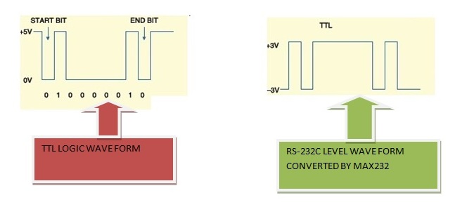
For example, most of the microcontrollers 8051(89c51,89c52), PIC(16f877), AVR works on TTL logic wave form. These microcontrollers have a build in UART(Universal Synchronous-Asynchronous Receiver & Transmitter) which can send and receive serial data. Since they work on TTL level so they transmit and receive data comprised of TTL wave from. Where as Standard PC(Personal Computers) works on RS-232 level wave form. Now if we need to transfer data from microcontroller to PC(Personal computer) we need to convert data from TTL to RS-232 level and if we want to send data from PC to microcontroller we have to convert data from Rs-232 to TTL. Max-232 is solution to this problem. Their is wide range where we use max232 but its main purpose is explained above.
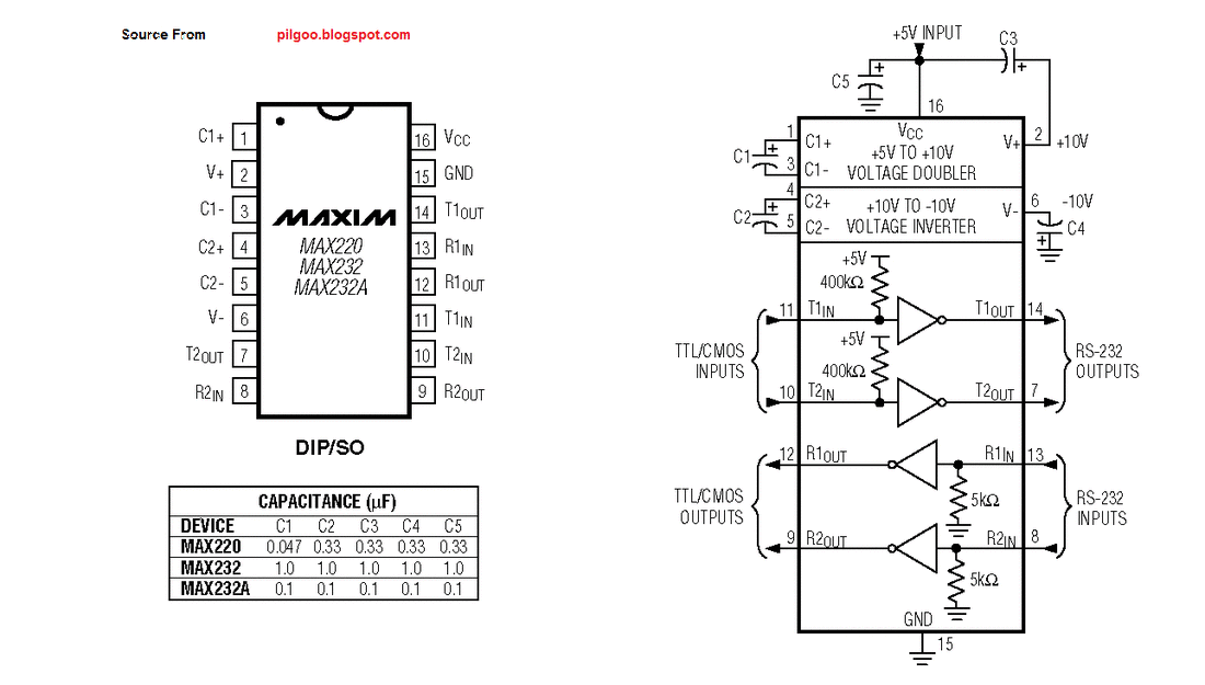
Pin names with Functions
PIN 1(C1+) Connect positive leg of a capacitor to it.
PIN 2(Vs+) Connect positive leg of a capacitor to it, and make negative leg of same capacitor ground.
PIN 3(C1-) Connect negative leg of a capacitor to it, whose positive leg is connected to Pin#1.
PIN 4(C2+) Connect positive leg of a capacitor to it.
PIN 5(C2-) Connect negative leg of a capacitor to it, whose positive leg is connected to Pin#4.
PIN 6(Vs-) Connect negative leg of a capacitor to it and apply 5 volts to positive leg of the same capacitor.
- PIN 7(T2OUT)
Outputs the converted TTL signal in RS-232 form. TTL signal is received from Microcontroller etc at T2IN Pin. Connect this pin to Pin#2 of DB-9 serial port of your PC. Pin#2 of DB-9 port is Rxd(Rxd means This pin receives Transmitted Signal(data)).
- PIN 8(R2IN)
This Pin receives RS-232 signal as input and outputs the converted signal in TTL form on pin R2OUT. Connect this pin to Txd pin of DB9 Port. Pin#3 of DB-9 port is Txd(Txd means This pin transmits data).
- PIN 9(R2OUT)
Outputs the converted signal in TTL form. Signal is recevied from Pc at R1In Pin. Connect this pin to your module(TTL) Rxd pin which receives the signal.
- PIN 10(T2IN)
Receives the transmitted signal from microcontroller(TTL Level) etc and outputs the converted RS-232 signal on T2OUT pin. Signal is transmitted from txd pin of microcontroller serial port. Connect this pin to your module Txd pin.
- PIN 11(T1IN) Woks same as T1IN.
- PIN 12(R1OUT) Works same as R2OUT.
- PIN 13(R1IN) Works same as R2IN.
- PIN 14(T1OUT) Works same as T2OUT.
- PIN 15(GND) Ground this pin.
- PIN 16(vcc) Apply 5 volts to this pin.
|
Max232 has two line drivers. You can make connections between four Uarts at a time. Diagram at the right side will clear you about line drivers, pin functions and connections. Data flow is clearly visible. Computer serial port db-9 is shown with max232, data flow between the two is visually explained.
|
Projects related to microcontrollers and Max232 serial Communication
|
Some projects related to microcontrollers and max232 interface are given. Please visit them to better understand the working of max232 interfaced with microcontrollers. All the projects are provided with free source code and circuit diagram. One can easily build and make the diy project by his own for his learning.
|
Filed Under: Knowledge Share, Microcontroller Projects


Questions related to this article?
👉Ask and discuss on Electro-Tech-Online.com and EDAboard.com forums.
Tell Us What You Think!!
You must be logged in to post a comment.