A galvanic skin-response (GSR) sensor is used to measure the stress levels or emotional spikes in people it’s reading by using two special electrodes. When in a reactive or stressed state, the human body’s sweat glands are activated. This sudden elevation in sweat can be picked up and recorded by the electrodes of a GSR sensor for further interpretation.
One of the most common applications for such skin-response sensors is a lie-detector test.

Although this technology has proven capable of detecting stress — which might be attributed to a person being deceptive or lying — there can be challenges in fine-tuning the sensor for a precise reading. For example, even a slight deviation in the electrodes could result in error spikes or malfunction. So, results should be evaluated with this in mind.
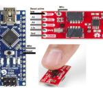
Nevertheless, this is an interesting do-it-yourself (DIY) project to experiment with. For this tutorial, we decided to use Seeed Studio’s GSR sensor module. Electrodes are attached to a wearable piece of cloth, which fits around a person’s finger. The sensitivity of the module is adjustable using an onboard potentiometer.
The sensor will output an analog signal that corresponds to the person’s skin conductance.
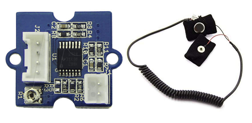
This sensor is compatible with 5v and 3.3v tolerance. For this project, we’re powering it will 5v of Arduino’s output.
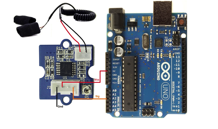
Circuit diagram
The code
Arduino’s analog pin #2 must be connected to the sensor’s output pin. As mentioned, Arduino’s regulator output (of 5v) is powering the sensor module. The electrodes are plugged into a jack connector.
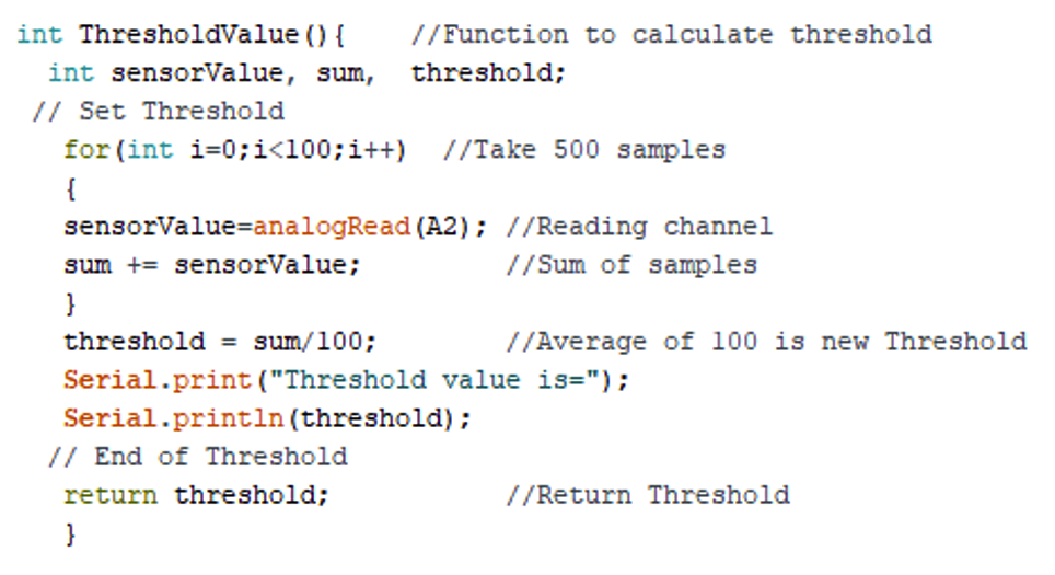
In the project code, we first initialized Arduino’s serial monitor, starting it at 9600bps. Then, to acquire the typical or “normal” conductance value of a person’s skin (i.e. their sweat levels), it’s necessary to declare a dedicated “ThresholdValue” function.
For this function, an average of 100 skin conductance samples is calculated and set as the typical threshold value.
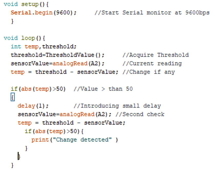
In the loop function, the subsequent skin/sweat values are acquired. These newer values are compared with the threshold and, if they’re different, a conductance message is sent as output via Arduino’s serial monitor.
These changes can be further studied and categorized. Here’s an example of a spike in the sensor’s reading.
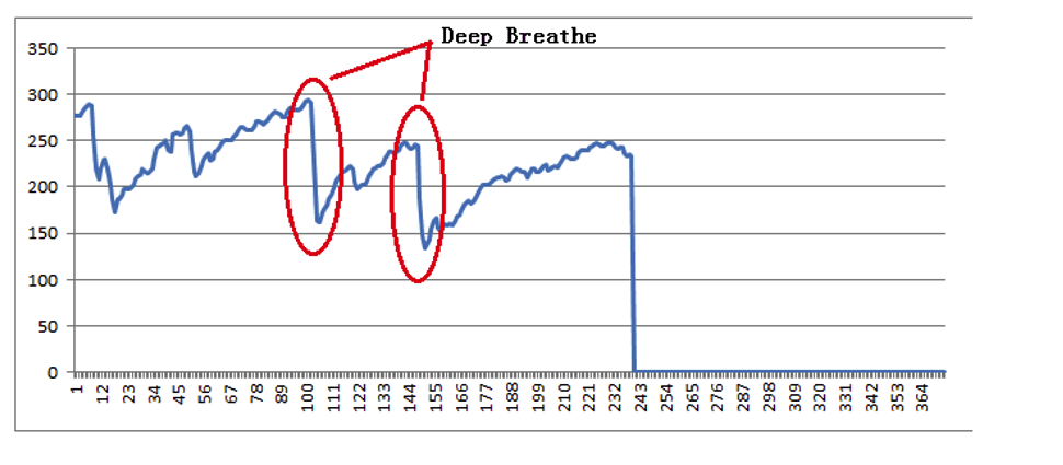
Source: Image link
Each sensor reading will differ based on the reference/threshold settings. For example, it will depend on how fast the underlying controller sets the reference and at what speed it interprets the new readings.
Where to purchase parts?
- DigiKey: GSR Sensor Kit
- DigiKey: Arduino UNO
You may also like:


Filed Under: Microcontroller Projects

Questions related to this article?
👉Ask and discuss on EDAboard.com and Electro-Tech-Online.com forums.
Tell Us What You Think!!
You must be logged in to post a comment.