The presence of dangerous LPG leakage in the cars, service station or in the storage tank environment can be detected using the Ideal Gas Sensor. This LPG gas leakage detector unit can be easily integrated into a unit that can sound an alarm or give a visual suggestion of the LPG concentration. The sensor has both admirable sensitivity and rapid response time. This sensor can also be used to sense other gases like iso-butane, propane, LNG and even cigarette smoke.
The output of the sensor goes LOW as soon as the LPG sensor senses any gas leakage from the storage. This is detected by the microcontroller and the LED & buzzer is turned ON. After the delay of few milliseconds, the exhaust fan is also turned ON for throwing the gas out and it continues sending message as ‘GAS LEAKAGE’ to a mobile number which is pre-defined.
INTRODUCTION
MQ-5 semiconductor sensor is Combustible Gas Sensitive. The MQ-5 gas sensor is made up of SnO2 which has lower conductivity in clean air. A simple electro-circuit is used here which is used to convert the changing conductivity into corresponding output signal of gas concentration. Both Methane and Propane can be detected easily by MQ-5 sensor because it has high sensitivity towards Methane, Propane and Butane. It is a low cost sensor suitable for different application.
BLOCK DIAGRAM FOR LPG GAS LEAKAGE DETECTOR
Block Diagram for Gas Leakage Detector
BLOCK DIAGRAM DESCRIPTION
MICROCONTROLLER
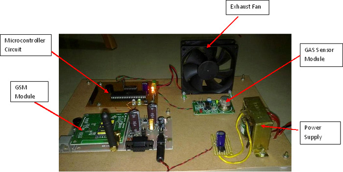
It is the heart of the project. It is used to control the Exhaust fan, LED and Buzzer when LPG leakage occurs. The input/ output ports of the microcontroller are used for this purpose.
MQ-5 LPG SENSOR
This sensor is used to sense the leakage of LPG. In normal conditions the output of this sensor is ‘high’ and it goes ‘low’, when the LPG is sensed.
EXHAUST FAN
The LPG is pushed out into the environment using an exhaust fan which reduces the concentration of LPG near the leakage area.
Buzzer
The leakage of the LPG is indicated by using the buzzer. It is 12 V DC operated buzzer.
LED
The leakage of the LPG is indicated by using the LED. It is 1.2 V DC operated LED.
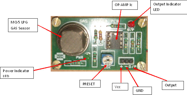
MQ-5 LPG GAS DETECTOR MODULE
Working Principle & Microcontroller Details
WORKING PRINCIPLE
In TGS gas sensors the sensing material is a metal oxide, most typically SnO2. The oxygen gets adsorbed on the crystal surface with a negative charge when the metal oxide crystal such as SnO2 is heated at a particular temperature in air. The donor electrons on the crystal surface are then transferred to the adsorbed oxygen which results in leaving positive charges in the space charge layer. Thus the surface potential serves as a potential barrier against the electron flow.
The electric current flows in the sensor through the combination parts (grain boundary) of SnO2 micro crystals. Adsorbed oxygen forms a potential barrier at the grain boundaries which prevents carriers to move freely. The electrical resistance of the sensor is recognized by this potential barrier. The surface density of the negatively charged oxygen decreases in the presence of deoxidizing gas which reduces the barrier height in the grain boundary. This reduced barrier height decreases the sensor resistance.
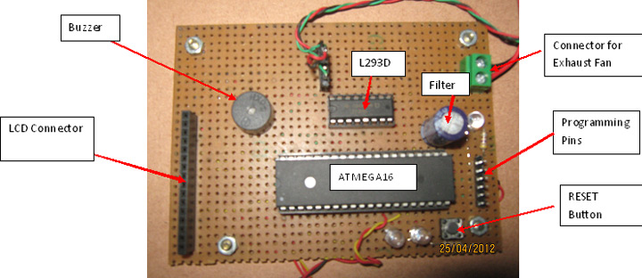
ATMEGA16 MICROCONTROLLER DETAILS
DESCRIPTION
The ATMEGA16 is a high-performance, low-power CMOS 8-bit microcomputer which has 16K bytes of Flash programmable and erasable read only memory (EPROM).The Atmel’s high-density nonvolatile memory technology is used to manufacture this device. It is also compatible with the industry-standard MCS-51 instruction set and the pin out. The on-chip flash also allows reprogramming in-system or it can also be done by a conventional nonvolatile memory programmer. The Atmel ATMEGA16 is a powerful microcomputer which provides a cost-effective and a highly-flexible solution to many embedded control applications by combining a versatile 8-bit CPU with the Flash on a monolithic chip,.
MICROCONTROLLER CIRCUIT WITH PHERIPHERALS
(NOTE: For more details of ATMEGA16, please refer datasheet.)
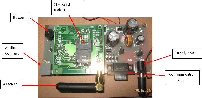
GSM Module
GSM MODULE
For sending message, a GSM Module named SIMCOM_300 with RS232, power supply, buzzer and audio interface are used. This can be connected to PC by using a USB to Serial Adaptor. Terminal programs such as Real term are used to send & receive data. The interface between GSM Module and microcontroller can also be done directly with the help of wires.
GSM Module works with AT COMMANDS where AT stands for Application Terminal.
Some useful AT Commands are:
1. AT
2. AT+CMGS
3. AT+CMGR
4. AT+CMGD
5. AT+CSQ?
And so on.
(For more details of AT COMMANDS, please refer AT COMMANDS List)
(NOTE: For more details of SIMCOM_300 GSM Module, please refer datasheet.)
CONNECTION BETWEEN MICROCONTROLLER AND GSM MODULE
For connection, Receiver Pin (Rx) of Microcontroller is connected to the Transmitter Pin (Tx) of GSM Module and Transmitter Pin (Tx) of Microcontroller is connected to the Receiver Pin (Rx) of GSM Module. Also Ground Pin (GND) of both are connected.

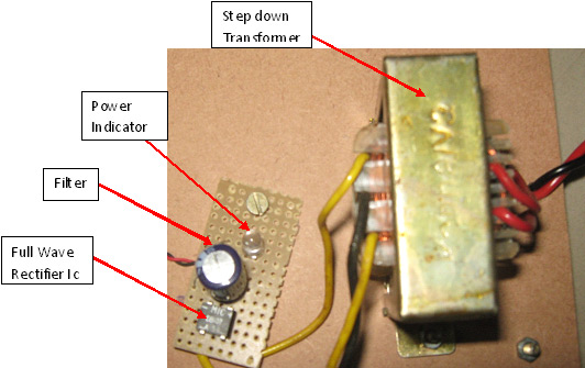
POWER SUPPLY
Power supply for the complete unit can be derived from the mains using a step-down transformer of 230V AC primary to 0-12V, 500mA secondary. A full- wave rectifier followed by a capacitor filter provides the output voltage and it is feed to the 5-volt regulator (LM7805) whose output is used as the power supply requirement for microcontroller circuit and other IC’s.
Circuit Diagram & Flow Chart
COMPLETE CONNECTION DIAGRAM
FLOW CHART DIAGRAM
APPLICATIONS
This project is applicable in following fields:
1. Gas leakage detector (Domestic)
2. Combustible gas detector (Industrial)
3. Gas detector (Portable)
4. Homes
5. Factories
6. LPG storage
7. Gas cars
8. Hotels etc.
Project Source Code
Circuit Diagrams
Project Datasheet
Filed Under: Electronic Projects

Questions related to this article?
👉Ask and discuss on Electro-Tech-Online.com and EDAboard.com forums.
Tell Us What You Think!!
You must be logged in to post a comment.