In most of the manufacturing industries, it is required to rotate DC/AC motor forward and reverse alternatively for desired time. First motor rotates forward (clockwise) for some time (say few minutes or even seconds). Then it stops for some time. Again it rotates reverse (anticlockwise) for some time and stops. This process continues. For example, in automated bottle filling plant, the bottles are moving on conveyor belt. When it comes under filler, the filler comes down (that means motor attached with mechanism rotates forward) then it fills the bottle (that means motor stops) again it goes up (motor rotates reverse) and stops until next bottle arrives. For moving filler up and down the time of rotating motor forward and reverse is calibrated and fixed. Also the motor stop time is calibrated based on time required to fill the bottle and the next bottle arrives.
Such motion of motor is controlled by sequential timer. Sequential timer circuit operates different processes one after another – means one process ends and it triggers next. The last process triggers first process when it ends. And thus the cycle continues. These sequence timers are micro controller based multi-functional and programmable. So operation time of each process can be programmed.
Here the given project demonstrates one such sequential timer controlled DC motor in which the forward rotation time, reverse rotation time and stop time for motor can be programmed. And then when process starts the motor starts rotating forward and reverse as per programmed time intervals. Some of the features of this project are
· 8-bit micro controller based fully programmable
· Process time can be set from 0 to 60 seconds
· LCD panel for display
· Timings can be set for 4 different process
· Can control 24 V DC motor or 230 V AC motor
· Push buttons for user interface
· User selectable single cycle or continuous operation
· LEDs for indications
Let us first understand system block diagram
System block diagram
Micro-controller 89S52: – It controls entire system by performing following tasks
- Accepts user inputs from push buttons to program DC motor running and stop timings
- Runs DC motor forward and reverse through driver circuit
- Shows different indication on indicators
- Displays different messages on LCD for time setting. It also displays remaining time for ongoing process
LED Indicators: – they indicates motor is running forward or reverse, motor is stop etc
LCD Panel: – it is used to display text, messages, time settings, time count down etc
Relay based motor driving circuit: – the motor runs – stops and it is rotated forward and reverse through relays. The relay contact connections are made such a way that as they switched ON/OFF the motor runs or stops and even alters its direction.

Fig. 1: Overview of 8051 Microcontroller based Sequential Timer for DC Motor Speed Control
Push buttons: – the circuit requires only 4 push buttons for different settings and user inputs
|
Sr no |
Button name |
function |
|
1 |
start |
To start rotating motor |
|
2 |
Increase time |
Increase time set by 1 sec – up to 60 sec |
|
3 |
Decrease time |
Decrease time set by 1 sec – up to 1 sec |
|
4 |
enter |
Enter set time |
Circuit Description and Software Program
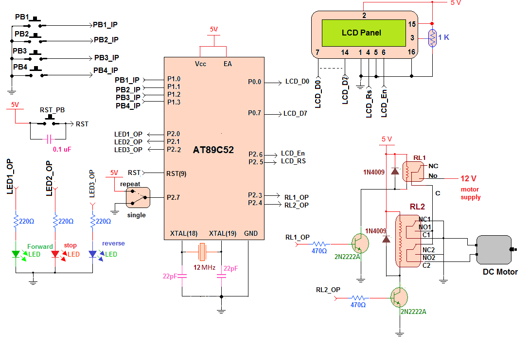
Circuit diagram:
· Four push buttons are connected to PORT1 pins P1.0 – P1.3 such that when any button is pressed that pin connects to ground and gets 0 input
· Three LEDs that indicates motor running forward-reverse or stop, are connected to PORT2 pins P2.0 – P2.2
· One SPDT switch is connected to pin P2.7 such that the pin gets either 0 or 1 input for continuous or single cycle operation
· Data pins D0-D7 of LCD are connected with PORT0. Control pins Rs and En are connected with pins P2.5 and P2.6 respectively. RW pin is connected to ground. One 1K pot is connected to VEE pin (3) to control LCD brightness
· Another two PORT2 pins P2.3 and P2.4 drives two relays RL1 and RL2 through two NPN transistors connected in switch configuration
· RL1 is single change over (1 C/O) relay and RL2 is 2 C/O relay. The motor is connected with two common terminals (C1 and C2) of RL2
· RL1 switches ON/OFF supply given to motor. RL2 terminals NC and NO are connected in such a way that when RL2 is off the motor rotates forward and when it is ON motor rotates reverse
· A 12 MHz crystal with two 22 pF capacitors is connected with crystal terminals as shown
· One reset pushbutton in parallel with 0.1 uF capacitor is connected to reset pin (9) as shown to provide manual reset to the micro controller
Circuit operation:
· When circuit is switched ON, all the LEDs are OFF and motor is stop. The message is displayed on LCD as “set forward time for motor:”
· User has to set time by pressing increase time/decrease time buttons. The time is increased or decreased in 1 second steps. After setting time he has to press enter
· When forward time is entered, the system displays message to enter reverse time for motor as “set reverse time for motor”
· Again user sets time using increase time/decrease time buttons and enters it
· Finally the system asks to enter stop time. When all three times are entered the system displays message “press start”
· The circuit operation starts when user presses start button
· The micro controller turns ON green LED (forward) and switches ON relay 1. So motor gets supply through relay 1 and relay 2 and starts running in one direction
· The message is displayed on LCD as “motor forward”. The time count down (of motor forward time) is also displayed
· When time count down finishes, micro controller turns OFF green LED, turns ON red LED (STOP) and switches OFF relay 1. So motor stops. The message is displayed “motor stop”. Again the count down (entered stop time) is displayed.
· Again when count down finishes, micro controller turns OFF red LED, turns ON blue LED (reverse) and switches ON both relays 1 and 2. This time motor gets reverse supply and starts running in reverse direction. The message is displayed “motor reverse” and the count down (of reverse time) starts.
· As the count down finishes, blue LED is turned OFF, red LED is turned ON and both relays are switched OFF. So motor stops. The message is displayed “motor stop”. Again the count down begins.
· Finally when stop time count down finishes, micro controller checks status of pin P2.7. if its 1 that means its repeat mode so the same above cycles continues till reset button is pressed. And if its 0 then its single cycle mode so user has to repeat complete process by entering all the timings again
Software program:
The complete circuit operation is due to the software program embedded inside micro controller. All the functionalities are implemented using software logic and the program. The program performs all the functionalities like
· Takes user inputs through push buttons and SPDT switch
· Displays different messages on LCD
· Displays time count down on LCD
· Give indications on 3 LEDs of motor running forward-reverse or motor stop
· Controls direction of motor to rotate it forward and reverse
· Runs and stops motor for fixed time interval entered by user as per requirements
The program is written in C language. It is compiled using KEIL (IDE) cross compiler tool. It is compiled for generic 8051 micro controller platforms so it can be used for all different micro controllers of MCS51 family like 89C51 / 89C52 / 89S52 etc. after compiling the program the HEX file is generated. That HEX file is loaded into the internal FLASH (EEPROM) of micro controller using any suitable EEPROM programmer.
Project Source Code
###
#include <reg51.h>
#include <string.h>
sbit rs = P2^5; // declare P2.5 as rs pin
sbit en = P2^6; // declare p2.6 as enable pin
sbit op1=P2^3; // output pins for relay
sbit op2=P2^4;
sbit fwd_led = P2^0; // LED pins
sbit rev_led = P2^2;
sbit stop_led = P2^1;
sbit pin=P2^7; // input pin for repeat or single cycle
unsigned char ascii[10] = {0x30,0x31,0x32,0x33,0x34,0x35,0x36,0x37,0x38,0x39};
unsigned int i=0;j=0,k=0,t1=0,t2=0,tmp1,tmp2,tmp3,tmp4,flag,sflag;
unsigned int ptime[4] = {0,0,0,0};
void writecmd(unsigned char a); // function to send command to LCD
void writedat(unsigned char b); // function to send data to LCD
void busy(); // function to check LCD is busy or not
void writestr(unsigned char *s); // function to write string on LCD
void keydly() // function for key debounce delay
{
int y,z;
for(y=0;y<50;y++)
for(z=0;z<1000;z++);
}
void writecmd(unsigned char a)
{
busy(); // check for LCD is busy or not
rs = 0; // clear rs pin for command
P0 = a; // send command character
en = 1; // strob LCD
en = 0;
}
void writedat(unsigned char b)
{
busy(); // check for LCD is busy or not
rs = 1; // set rs pin for data
P0 = b; // send data character
en = 1; // strob LCD
en = 0;
}
void busy()
{
int o;
for(o=0;o<2000;o++);
}
void writestr(unsigned char *s)
{
unsigned char l,i;
l = strlen(s); // get the length of string
for(i=0;i<l;i++)
{
writedat(*s); // write every char one by one
s++;
}
}
void inctime()
{
t2=0; // minimum limit flag cleared
if(k==1) // check to increase ontime or offtime
{
if(ptime[1]<60) ptime[1]++; // increase offtime till 60
else
{
writecmd(0xC0);
writestr("60-max limit "); // if it is 60 display message
t1=1; // and set max limit falg
}
i=ptime[1]/10; // separate upper and
j=ptime[1]%10; // lower digits
}
else if(k==2) // if ontime-offtime flag is not 1
{
if(ptime[2]<60) ptime[2]++; // increase ontime till 60
else
{
writecmd(0xC0); // same as above
writestr("60-max limit ");
t1=1;
}
i=ptime[2]/10;
j=ptime[2]%10;
}
else if(k==3) // if ontime-offtime flag is not 1
{
if(ptime[3]<60) ptime[3]++; // increase ontime till 60
else
{
writecmd(0xC0); // same as above
writestr("60-max limit ");
t1=1;
}
i=ptime[3]/10;
j=ptime[3]%10;
}
else // if ontime-offtime flag is not 1
{
if(ptime[0]<60) ptime[0]++; // increase ontime till 60
else
{
writecmd(0xC0); // same as above
writestr("60-max limit ");
t1=1;
}
i=ptime[0]/10;
j=ptime[0]%10;
}
if((t1==0)&& (t2==0)) // if max limit is not reached
{
writecmd(0xCA); // print ontime/offtime sec
writedat(ascii[i]); // as one by one digit
writedat(ascii[j]);
}
}
void dectime() // similar to above function
{
t1=0;
if(k==1)
{
if(ptime[1]>1) ptime[1]--;
if(ptime[1]<=1)
{
writecmd(0xC0);
writestr("01-min limit ");
t2=1;
}
i=ptime[1]/10;
j=ptime[1]%10;
}
else if(k==2)
{
if(ptime[2]>1) ptime[2]--;
if(ptime[2]<=1)
{
writecmd(0xC0);
writestr("01-min limit ");
t2=1;
}
i=ptime[2]/10;
j=ptime[2]%10;
}
else if(k==3)
{
if(ptime[3]>1) ptime[3]--;
if(ptime[3]<=1)
{
writecmd(0xC0);
writestr("01-min limit ");
t2=1;
}
i=ptime[3]/10;
j=ptime[3]%10;
}
else
{
if(ptime[0]>1) ptime[0]--;
if(ptime[0]<=1)
{
writecmd(0xC0);
writestr("01-min limit ");
t2=1;
}
i=ptime[0]/10;
j=ptime[0]%10;
}
if((t1==0)&& (t2==0))
{
writecmd(0xCA);
writedat(ascii[i]);
writedat(ascii[j]);
}
}
void enter() // enter ontime & offtime and
{ // display message
k++; // increase count to enter off time
if(k==1) // first time
{
writecmd(0x80);
writestr("set reverse time"); // display message and
writecmd(0xC0); // show value 00
writestr("for motor:");
writedat(0x30);
writedat(0x30);
i=j=0;
}
else if(k==2)
{
writecmd(0x80);
writestr("set stop time "); // display message and
writecmd(0xC0); // show value 00
writestr("for motor:");
writedat(0x30);
writedat(0x30);
i=j=0;
}
else if(k==3) // second time
{
writecmd(0x01); // clear LCD screen and
writestr("Press start"); // display message
k=0; // reset counter
sflag=1;
}
}
void delay1sec() // generate delay of aprox 1 sec
{
int k;
TL1 = 0xCD;
TH1 = 0x3C;
TR1 = 1;
for(k=0;k<=20;k++)
{
while(TF1==0);
TF1 = 0;
TL1 = 0xCD;
TH1 = 0x3C;
}
TR1 = 0;
}
void start()
{
int a;
tmp1=ptime[0]; // save ontime and offtime values
tmp2=ptime[1];
tmp3=ptime[2]; // save ontime and offtime values
tmp4=ptime[3];
back:writecmd(0x80);
writestr("motor forward"); // display message
op1=1; // switch ON relay
for(a=tmp1;a>0;a--) // start countdown
{
i=a/10;
j=a%10;
writecmd(0xC0);
writedat(ascii[i]); // change the display digits
writedat(ascii[j]); // on LCD after
delay1sec(); // every sec
}
op1=0; // switch OFF relay
writecmd(0x01);
writestr("motor stop"); // display message
for(a=tmp3;a>0;a--) // start countdown again
{
i=a/10;
j=a%10;
writecmd(0xC0);
writedat(ascii[i]); // display digits after
writedat(ascii[j]);
delay1sec(); // 1 sec delay
}
op1=1;
op2=1;
writecmd(0x80);
writestr("motor reverse");
for(a=tmp2;a>0;a--) // start countdown again
{
i=a/10;
j=a%10;
writecmd(0xC0);
writedat(ascii[i]); // display digits after
writedat(ascii[j]);
delay1sec(); // 1 sec delay
}
op1=0; // switch OFF relay
op2=0;
writecmd(0x01);
writestr("motor stop");
for(a=tmp3;a>0;a--) // start countdown again
{
i=a/10;
j=a%10;
writecmd(0xC0);
writedat(ascii[i]); // display digits after
writedat(ascii[j]);
delay1sec(); // 1 sec delay
}
if(pin==1) goto back; // repeat continuously for repeat mode
else // otherwise
{
flag=1; // set flag
ptime[0]=0; // clear ontime and offtime
ptime[1]=0; // and stop operation
ptime[2]=0;
ptime[3]=0;
}
}
main()
{
TMOD=0x10;
P0=0x00;
P2 = 0x10;
writecmd(0x3C); // Initialize LCD
writecmd(0x0E);
bgin: writecmd(0x01); // clear display
writestr("set forward time"); // display message and
writecmd(0xC0);
writestr("for motor:");
writedat(0x30); // value as 00
writedat(0x30);
flag=0;
sflag=0;
agin:P3=0xFF; // P1 as input
while(P3==0xFF); // for keypad mode check status of P1
switch(P3) // compare the content of byte
{
case 0x7F:
if(sflag==1) start(); // for 1st key start operation
else
{
writecmd(0xC0);
writestr("time is not set");
flag=1;
}
break;
case 0xBF:
inctime(); // for 2nd key increase time break;
case 0xDF:
dectime(); // for 3rd key decrease time break;
case 0xEF:
enter(); // for 4th key enter values break;
}
keydly(); // key debounce delay
if(flag==0) goto agin; // till start button is not pressed change and
else goto bgin; // enter values otherwise start operation again
}
###
Circuit Diagrams
Project Video
Filed Under: Electronic Projects
Filed Under: Electronic Projects

Questions related to this article?
👉Ask and discuss on EDAboard.com and Electro-Tech-Online.com forums.
Tell Us What You Think!!
You must be logged in to post a comment.