In the previous tutorial, we learned how to interface a DHT-11 sensor with Arduino. DHT-11 is a digital sensor that comes integrated with an 8-bit microcontroller. This integrated microcontroller outputs humidity and temperature values in the form of a 40-bit digital data packet.
In the last tutorial, we read the data packet by polling one of Arduino’s digital I/O pins and detected data bits by measuring the pulse width of the digital signal. However, this is not the typical way digital sensors output data. Most digital sensors use standard data communication protocols, such as UART, SPI, or I2C to communicate data with a controller/computer.
The universal asynchronous receiver/transmitter (UART) protocol is the most common data communication protocol that’s available on nearly all embedded devices. Most of the embedded devices use the UART for exchanging console data. Alternatively, they may be using I2C for the same purpose. It just depends if the device is meant to be a peer device or a slave to a computer system.
Digital sensors are no different. Almost all digital sensors that interface with a controller/embedded computer as a peer device use the UART. This is particularly true for those sensors and devices that involve bidirectional data communication with a computer system. However, the majority of sensors are designed to only transmit data to a controller/computer system as a slave and may use serial protocols, such as I2C or SPI for communicating sensor data. (Learn about the basics of serial communication from this Raspberry Pi tutorial.)
All Arduino boards have one or more of the UART ports. Arduino also offers a Serial feature that’s a software implementation of the UART protocol on digital I/O pins. But softwareSerial is incompetent with a hardware UART. So, let us discuss Arduino’s UART feature.
What is the UART?
The universal asynchronous receiver/transmitter (UART) is a circuit that communicates with point-to-point data (half-duplex or full-duplex) over a UART protocol. The circuit is available as a standalone ICs and typically comes integrated peripherally in microcontrollers and embedded computers.
The UART protocol
You can learn about the UART protocol here.
UART/USART in Arduino(s)
Serial ports are used for data communication with computers or other devices. All Arduino boards have one or more serial ports that can be UART or USART.
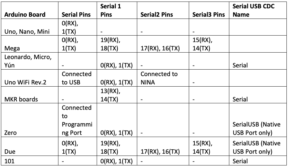
This table lists the UART ports on different Arduino boards:
The TTL voltage level of Arduino’s UART can be 5 or 3.3V, depending on the respective board. While connecting the serial port of one device with the other, the UART voltages should be compatible. If a serial port with a higher UART voltage level (TTL) is connected to a serial port of a lower UART voltage level (TTL), the higher TTL will still be able to receive serial data. However, when it transmits serial data, to the Rxd pin of the lower UART voltage port, it will get damaged.
Therefore, a suitable TTL Level shifter must be used when connecting two UART ports of different TTL voltage levels.
When two compatible UART ports are directly connected, the Txd and Rxd of one device connect to the Rxd and Txd of the other device — while sharing the same ground. If two UART ports are connected via a TTL logic shifter, the connections will then depend on the pin configuration of the TTL logic shifter.
If the UART port is connected to a different interface, such as a USB or RS-232, a suitable serial converter must be used (for example, the RS-232-serial board for RS-232 interfaces and the USB-serial boards for USB interfaces).
This is particularly important for the RS-232 interfaces because they communicate data over the UART protocol. These interfaces can easily be hacked to expose the Rxd and Txd pins. These pins use positive and negative voltages, ranging from -15V to 15V for the logical bits. If the Rxd and Txd pins of an RS-232 port are directly connected to a TTL UART port, the TTL port will be destroyed.
On Uno, Nano, Mini and Mega boards, the serial port pins 0 and 1 are used by the USB for communication with computers. If these pins are engaged, it may interfere with serial communication over the USB. For example, if something is connected to these pins, it may not be possible to upload a sketch to the board from a computer.
When connecting to other serial ports (if available like on the Mega and Due boards), these ports can only be connected to a computer through a USB-serial board. The other serial ports are not connected to Arduino’s USB.
The UART through GPIO pins
Arduino’s built-in UART connects to the GPIO pins. A serial port has two channels:
- Txd for transmitting serial data
- Rxd to receive serial data, according to the UART protocol
Both devices communicating through the UART should have the same baud rate and data encoding. If configured to different baud rates or encoding, they will not be able to exchange data or the data exchanged will be gibberish.
The UART through Arduino USB
Arduino can also communicate serial data over a USB. However, the USB interface does not exchange data over the UART protocol. Rather, the USB has a different data communication standard that requires one device to be configured as the host and the other device as a slave.
The data is communicated as packets in the USB standard and the UART communicates data as characters. There’s nothing similar to the baud rate in USB communication.
If you recall, Arduino has two controllers. One controller is responsible for handling USB communication. Arduino’s USB port is available to program it by using computers. This additional controller serves as a built-in USB-serial converter when data is communicated serially using Arduino’s USB port.
Arduino’s UART/USART is also connected to this additional controller, which converts the UART data to the USB. When Arduino is connected to a computer via a USB cable, it acts as a CDC/ACM device over the USB. This is similar to serial communication with a PC. In some Arduino boards, USB communication is not handled by the additional controller but is managed by the main controller onboard. With these boards, Arduino identifies itself as a USB CDC slave.
When Arduino is connected to a Mac, it uses a device name, such as /dev/tty.wchusbserial*, where the asterisk (‘*’) may be any number. On Linux systems, it may appear with a device name, such as /dev/ttyACM*. where the asterisk is any number. On Windows, it may appear by a port name, such as COM*, where the asterisk is any number.
Serial library
The Arduino platform supports the Serial library for UART communication. This library has the following methods:
Serial.begin() – used to configure serial communication over the serial port. It’s used to set the baud rate and UART configuration. This method has this syntax:
Serial.begin(speed)
or
Serial.begin(speed, config)
The baud rate can be any standard baud rate with a maximum value of 115200 bps. The default UART configuration is 8N1.
The configuration can be set to these arguments:
SERIAL_5N1, SERIAL_6N1, SERIAL_7N1, SERIAL_8N1 (the default), SERIAL_5N2, SERIAL_6N2, SERIAL_7N2, SERIAL_8N2, SERIAL_5E1, SERIAL_6E1, SERIAL_7E1, SERIAL_8E1, SERIAL_5E2, SERIAL_6E2, SERIAL_7E2, SERIAL_8E2, SERIAL_5O1, SERIAL_6O1, SERIAL_7O1, SERIAL_8O1, SERIAL_5O2, SERIAL_6O2, SERIAL_7O2 and SERIAL_8O2.
In the Arduino boards that identify as USB CDC slaves, such as Leonardo, the Serial.begin() is irrelevant. Such boards can use any configuration and baud rate for the UART. The source code of this method is available in the Arduino/hardware/arduino/avr/cores/arduino/HardwareSerial.cpp.
The Serial.begin() method has this source code:

if(Serial) or if(SerialUSB) – these if statements can be used to find out if the serial port is ready. For non-USB CDC ports, if(Serial) is used. For the USB-CDC ports, if(SerialUSB) is the test condition. If the port is ready, the condition will return True. If the port does not exist — say, a particular Arduino board does not have a USB CDC port or, it does, but it’s not ready — the condition will return False.
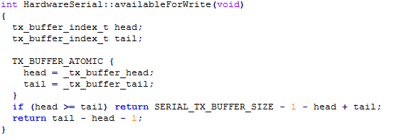
Serial.availableForWrite() – returns the number of bytes (characters) available for writing in the serial buffer without blocking the write operation. It has this syntax:
Serial.availableForWrite()
For the Arduino boards that have multiple serial ports, the function takes the serial port object as the argument.
This method has this source code:
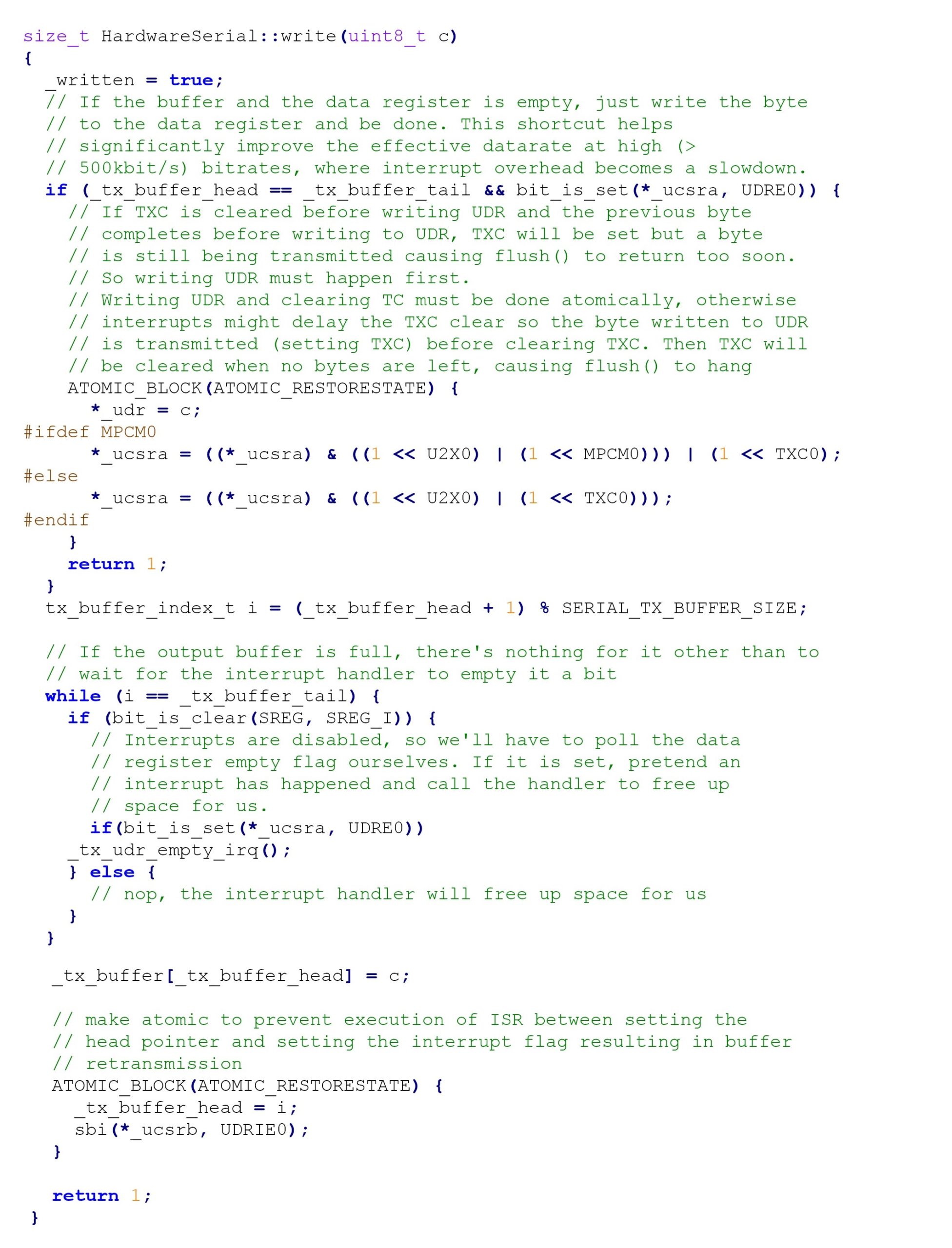
Serial.write() – used to send binary data to the serial port. The data is sent as a byte or series of bytes. This method has this syntax:
Serial.write(val)
or
Serial.write(str)
or
Serial.write(buf, len)
This method requires a value (single byte) or string (series of bytes) as a parameter. If an array is passed as an argument (buf), the length of the array (len) should also be passed as the argument.
For the Arduino boards with multiple serial ports, the function takes the serial port object as the argument. The function will return the number of bytes written to the port, however, reading this number is optional.
This method has this source code:
Serial.print() – used to send the ASCII characters to the serial port. This function needs a value or string as an argument. It also accepts BIN, OCT, DEC, or HEX as optional arguments to specify the base format (binary, octal, decimal, or hexadecimal) of the characters. If the value passed is a floating-point number, the number of decimal places can be passed as the argument. This function has this syntax:
Serial.print(val)
or
Serial.print(val, format)
For the Arduino boards with multiple serial ports, the function takes the serial port object as the argument. This function returns the number of bytes written to the port but reading this number is optional.
Serial.println() – this method is same as the print() except of the sent ASCII characters but followed by a carriage return (‘\r’) and a newline character(‘\n’). It has this syntax:
Serial.println(val)
or
Serial.println(val, format)
Serial.available() – checks if serial data is available to read from the serial port. This is data that’s already arrived and stored in the 64-byte serial receive buffer. This method inherits from the Stream utility class. It has this syntax:
Serial.available()
The function returns the number of bytes available to read from the receive serial buffer.
This method has this source code:

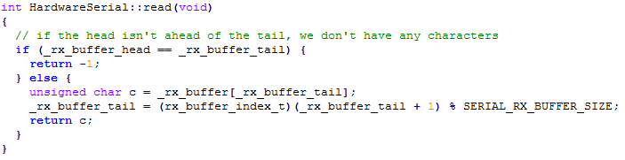
Serial.read() – used to read incoming data from the serial port. It has this syntax:
Serial.read()
It returns the first byte of incoming serial data available or -1 if no data is available.
This function has this source code:
Serial.peek() – this method returns the next byte (character) of the incoming serial data without removing it from the internal serial buffer. It has this syntax:
Serial.peek()
This method has this source code:

Serial.readBytes() – reads characters from the serial port into a buffer. It terminates if the determined length has been read or there is a timeout. It has this syntax:
Serial.readBytes(buffer, length)
Serial.readBytesUntil() – reads characters from the serial buffer into an array. It terminates if the determined length has been read, if there is a timeout, or if the terminator character is detected. The terminator itself is not returned in the buffer. This method has this syntax:
Serial.readBytesUntil(terminator character, buffer, length)
Serial.readString() – reads characters from the serial buffer into a String. It terminates if there is a timeout. It has this syntax:
Serial.readString()
Serial.readStringUntil() – reads characters from the serial buffer into a String. It terminates, if there is a timeout or if the terminator character is detected. It has this syntax:
Serial.readStringUntil(terminator)
Serial.setTimeout() – sets the maximum milliseconds to wait for the serial data. The default timeout is 1000 milliseconds. The following methods use it: Serial.find(), Serial.findUntil(), Serial.parseInt(), Serial.parseFloat(), Serial.readBytes(), Serial.readBytesUntil(), Serial.readString(), Serial.readStringUntil(). It has this syntax:
Serial.setTimeout(time)
Serial.find() – reads data from the serial buffer until the target string is found. It returns true if the target string is found and false if it times out. It has this syntax:
Serial.find(target)
or
Serial.find(target, length)
Serial.findUntil() – reads data from the serial buffer until a target string of given length or a terminator string is found. It returns true if the target string is found and false if it times out. It has this syntax:
Serial.findUntil(target string to search, terminator string)
Serial.flush() – causes the serial port to wait for the transmission of outgoing serial data to complete. It has this syntax:
Serial.flush()
This method has this source code:

Serial.readBytes() – reads characters from the serial port into a buffer. It terminates if the determined length has been read or there is a timeout. It has this syntax:
Serial.readBytes(buffer, length)
Serial.readBytesUntil() – reads characters from the serial buffer into an array. It terminates if the determined length has been read, if there is a timeout, or if the terminator character is detected. The terminator itself is not returned in the buffer. This method has this syntax:
Serial.readBytesUntil(terminator character, buffer, length)
Serial.readString() – reads characters from the serial buffer into a String. It terminates if there is a timeout. It has this syntax:
Serial.readString()
Serial.readStringUntil() – reads characters from the serial buffer into a String. It terminates, if there is a timeout or if the terminator character is detected. It has this syntax:
Serial.readStringUntil(terminator)
Serial.setTimeout() – sets the maximum milliseconds to wait for the serial data. The default timeout is 1000 milliseconds. The following methods use it: Serial.find(), Serial.findUntil(), Serial.parseInt(), Serial.parseFloat(), Serial.readBytes(), Serial.readBytesUntil(), Serial.readString(), Serial.readStringUntil(). It has this syntax:
Serial.setTimeout(time)
Serial.find() – reads data from the serial buffer until the target string is found. It returns true if the target string is found and false if it times out. It has this syntax:
Serial.find(target)
Serial.parseFloat() – returns the first valid floating-point number from the Serial buffer. This function terminates after detecting the first character that’s not a floating-point number or when it times out. It has this syntax:
Serial.parseFloat()
or
Serial.parseFloat(lookahead)
or
Serial.parseFloat(lookahead, ignore)
The argument ‘lookahead’ sets the mode used to look ahead in the stream for a floating-point number. This argument can take values: SKIP_ALL, SKIP_NONE, and SKIP_WHITESPACE. The argument ‘ignore’ is used to skip the indicated char in the search.
Serial.parseInt() – this method is similar to the Serial.parseFloat(). It returns the first valid integer from the Serial buffer. It also terminates if it times out. It has this syntax:
Serial.parseInt()
or
Serial.parseInt(lookahead)
or
Serial.parseInt(lookahead, ignore)
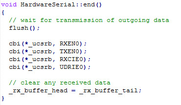
Serial.end() – disables serial communication, allowing the RX and TX pins to be used for general input and output. The pins are enabled for serial communication only when the Serial.begin() is called. It has this syntax:
Serial.end()
It has this source code:
Interfacing Arduino with a computer
The easiest way to interface Arduino with a computer is to use a USB-to-USB cable. If other serial ports are to connect with computer, a USB-to-serial board must be used.
Serial monitor
Arduino IDE has an integrated serial monitor that can be used to receive and send serial data via the USB ports of the desktop computer. The serial monitor can be opened by navigating to Tools->Serial Monitor.
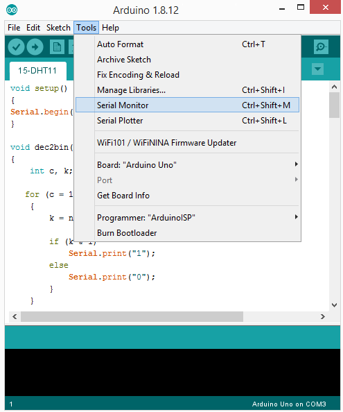
It can also be accessed by clicking the Serial Monitor icon on the top-right corner of the IDE.
![]()
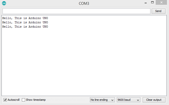
When launching the Serial Monitor, a window opens where serial data can be sent to, received, and viewed from the connected serial device. The baud rate and encoding can also be set from within the window.

Transmitting data to the computer
The result
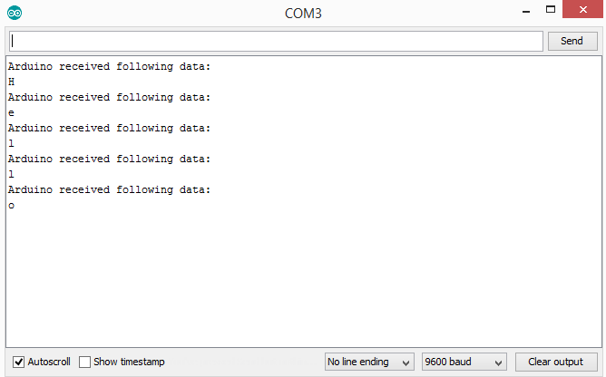
Receiving data from the computer
The result
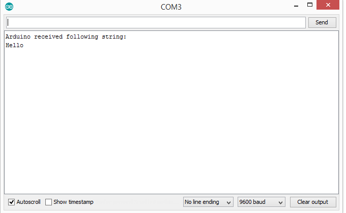
Receiving data strings from computer
The result
The Serial Plotter
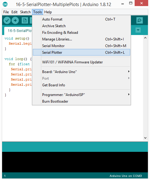
Arduino IDE has an integrated serial plotter that can be used to visualize the received data graphically. It can be opened by navigating to Tools->Serial Plotter.
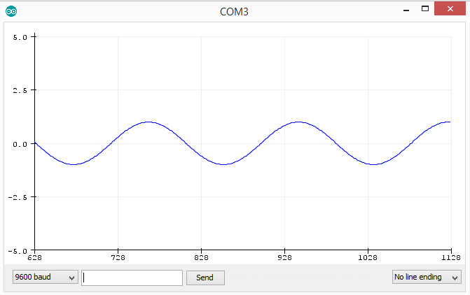
Plotting a single variable on the Serial plotter
To plot a single variable, the Arduino sketch must print a single variable to the Serial port within the loop() function.
Check out the sketch below, which plots a sine wave on the Serial Plotter:
The result
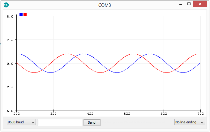
 Plotting multiple variables on the Serial Plotter
For plotting multiple variables or waveforms simultaneously on the Serial Plotter, a ‘space’ should be printed between the two print functions.
Check out the following sketch that plots a sine and cosine wave on the Serial Plotter.
The result
In the next tutorial, we’ll learn about softwareSerial in Arduino.
Filed Under: Arduino

Questions related to this article?
👉Ask and discuss on EDAboard.com and Electro-Tech-Online.com forums.
Tell Us What You Think!!
You must be logged in to post a comment.