Spy cameras are mainly used for surveillance activities and to ensure safety. They may also be used for commercial purposes, such as to monitor for theft or break-ins at a store or workplace.
Typical cameras are bulky and can be easily be spotted. However, it’s possible to integrate them into another object. To fit one into a wall painting, for instance, it’s first necessary to consider the size and dimension match.
In this tutorial, we’ll learn how to integrate a camera with Arduino.
Considerations
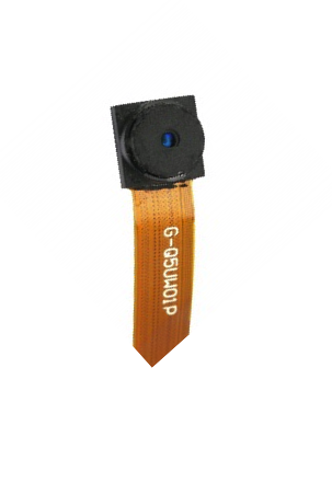
The camera module.
Before getting started, it’s important to go over a few things:
- The camera module. The physical camera module is small, which means it’s necessary to first remove all of the casings.
- The storage module. Recording a video or even storing images requires plenty of storage space to do so. Storage technologies, such as EEPROM, FLASH, or SDCARD offer a fairly large size for storage. Smaller EEPROMS chip sizes exist but are not feasible to use in DIY projects.
- The power module. Power is another important consideration. Spy cameras must be powered for a long period of time. Also, the standard cell/battery size is much larger than a camera module so we’ll have to consider the options.
One way to save power and storage is to take images on a timed interval, rather than recording an ongoing video. Then, it’s possible to cascade the images in ascending order, generating a video from these images.
In this tutorial, we’re using the Adafruit mini spy camera. This module includes a camera, an SDCARD slot, and power cables. What’s nice about this choice is that it’s unnecessary to program the Adafruit camera. To capture images, we simply need to ground a wire.
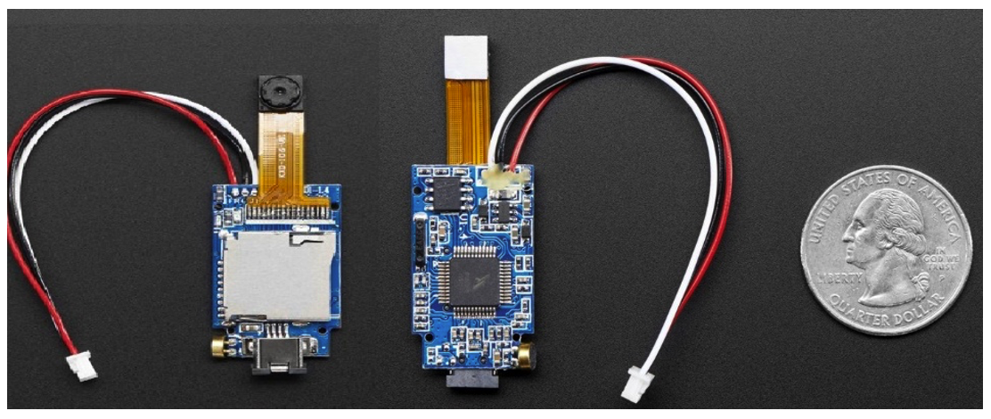
A battery is the only device required to power the module. You’ll note the one we used is nearly equivalent to the camera module size (about the size of a quarter).

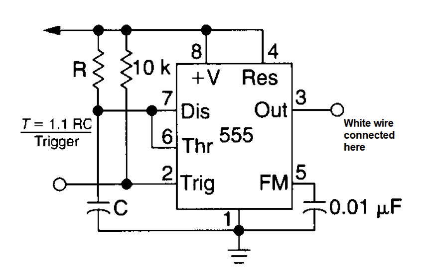
Now, to take images simply attach the white wire to the ground. The camera will snap images every half-second, which is predefined in the camera controller. It’s not possible to change this setting, but you can increase the time delay by using an external circuit that grounds the white wire after the preferred delay.
A 55 IC can be used to generate the desired trigger for the image capture. Select the input resistor and capacitor value for the desired delay. The equation for the delay calculation is given in the circuit.
The circuit
Of course, another possibility is to use a microcontroller, which can be programmed. For this project, let’s use Arduino.
First, you’ll need to define a single pin and toggle it after the desired time.
The code
const byte camPin = 2; // Camera white wire connected to Arduino pin#2
void setup() {
pinMode(camPin, OUTPUT);//Capture pin declared as output
}
void loop() {
!digitalWrite(camPin); //Toggling capture pin after every 5 seconds
delay(5000); //5 second delay
}
Another idea is to shoot the images at random intervals. The Arduino loop function should then look like this:
void loop() {
!digitalWrite(camPin); //Toggling capture pin after every 5 seconds
delay(random(1000,10000)); // Select random delay between 1 to 10 seconds
}
What’s required
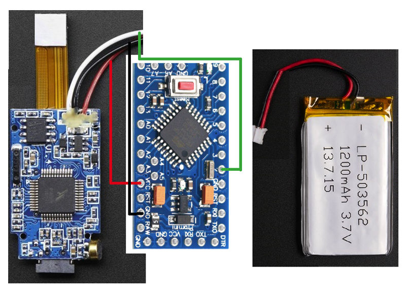
- Arduino – we used Arduino Nano as it’s compact
- One camera module – we used the Adafruit mini spy camera
- One battery
The interconnections between the three peripherals are straightforward. One battery can easily power both the modules. The camera module’s white wire connects with the Arduino’s pin#2.
In this case, the size of the spy camera is still somewhat large. It’s possible to define and custom-generate each module by using FPGA and then printing the custom module. That is a tedious task, however.
Where to purchase the parts?
Filed Under: Microcontroller Projects

Questions related to this article?
👉Ask and discuss on EDAboard.com and Electro-Tech-Online.com forums.
Tell Us What You Think!!
You must be logged in to post a comment.