The idea of noninvasive current measurement is not new. Commercial devices are available which can measure current without any physical contact. However, the topic was not popular among the DIY community because of the complexity and nonexistence of the compact non-invasive sensors, which could be studied at low power. Luckily, we have small and reliable current transformers that can be used to measure alternating current without physical contact.
Current transformers (CT) have the same physical parts as a regular transformer. They are split-core means primary and secondary coils can be separated. They differ from regular transformers on working principle. The primary coil induces a current in the secondary, proportional to current passing intensity through the primary (Electromagnetic induction).
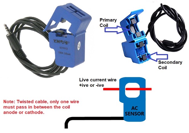
A CT sensor is shown above. Split cores can be seen with a permanent magnet. We open the cores and place a live current-carrying wire in between and then close the cores. Note that we only place anode or cathode in between the cores. Inserting both the wires at once will yield no or misleading results. Why?
Current flows from anode to cathode. If we place both the wires simultaneously in the core, then the anode will cancel the cathode electrical field due to opposite polarity. Hence one wire is needed to measure the current. Recall when measuring current physically with a digital multimeter (DMM), we cut the wire and place the DMM probes in series. Same we did in the CT case, just the physical contact is not made.
Current transformers output current or voltage, which is directly proportional to the input current. Output current is an RMS (root mean square), and voltage is in AC form. We need to convert both the quantities in DC to measure them using Arduino or any other microcontroller.
Let’s begin
I decided to use Arduino and a predefined library named “Emon” energy monitor to measure the current flowing through a live wire. To make CT output compatible with Arduino, we must transform it into digital form. We have few options here.
- Rectify the output signal using a diode bridge and then amplify it. Amplify? Because the output of CT is 0-1v or 0-50mA depending on the type.
- Using an offset voltage to raise the CT output to a level acceptable by Arduino. Offset is raised using a voltage divider and a solo capacitor.
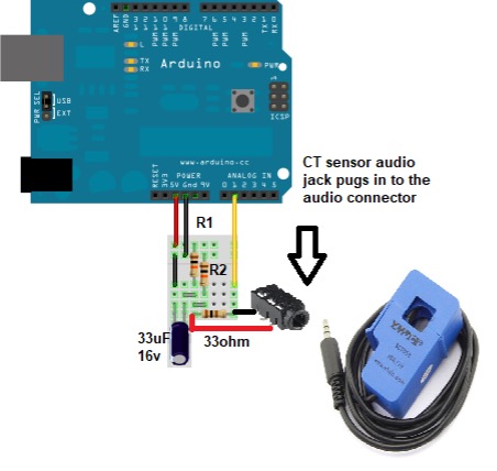
The “Emon” library implements the second method. So, we will use that. How to offset is raised, and the load resistance is explained in the picture below.
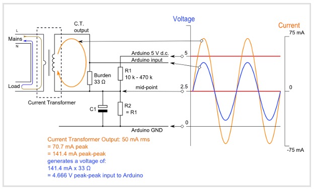
Source: https://learn.openenergymonitor.org/electricity-monitoring/ct-sensors/interface-with-arduino
Current transformer is rated at input 0-100A output 0-50mA. Focus on the midpoint. The sensor output is added to a midpoint.
At max VCT=IR where I=70mA & R=33ohm VCT= 2.31 volts. VMidPoint= 2.5 +2.31 = 4.81-volt max.
The voltage output current transformer burden resistor is not required. It already has an internal resistor rest of the circuit.
Project code:
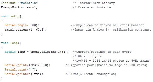
First, download the Emon library and install it for Arduino ide. Create a new project, include the EmonLib header file, and create an instance. In the setup function, I started the serial monitor at 9600 bps. The next statement emon1.current(1,60.6), is declaring the analog-1 pin of Arduino UNO as input (CT output is connected to A1 of Arduino UNO) 60.6 is calibration constant (will discuss later).
In the loop function emon1.calcIrms(1484) statement is calculating the current. In each input power cycle (50Hz), 106 instances of current are read by the Emon library. For better precision, I want to grab current instances for 14 cycles which are equal to 1484. Finally, the Irms variable is used to store the result. Once current is known, apparent power can be calculated by multiplying current with 230 mains voltage.
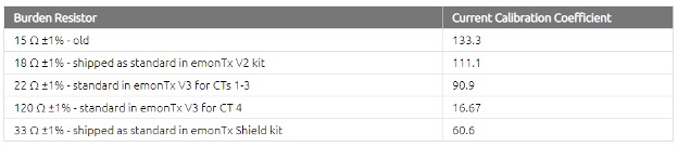
CT and burden resistance are not accurate; there is some margin of error. Emon specified the formula and default calibration values for known resistances and CT to cover up this margin of error. In our case, we used 33-ohm burden resistance, CT max input is 1000A and output 50mA. Calibrated value can be calculated using the formula below.
Project circuit diagram:
 Build the circuit and upload the code in Arduino. It connects the CT to live wire, and open Arduino serial monitor current values will start displaying on Arduino serial monitor.
Let’s DIY it: Where to purchase parts?
DigiKey: Current transformer
DigiKey: Arduino un
DigiKey: Audio Jac
DigiKey: Resistor
DigiKey: Capacitor
You may also like:

Filed Under: Arduino, Microcontroller Projects

Questions related to this article?
👉Ask and discuss on Electro-Tech-Online.com and EDAboard.com forums.
Tell Us What You Think!!
You must be logged in to post a comment.