Engineers Garage

  • Projects and Tutorials
    • Circuit Design
    • Electronic Projects
      • 8051
      • Arduino
      • ARM
      • AVR
      • PIC
      • Raspberry pi
      • STM32
    • Tutorials
    • Components
  • Articles
    • Tech Articles
    • Insight
    • Invention Stories
    • How to
    • What Is
  • News
    • EE Design News
    • DIY Reviews
    • Guest Post
    • Sponsored Content
  • Forums
    • EDABoard.com
    • Electro-Tech-Online
    • EG Forum Archive
  • Digi-Key Store
    • Cables, Wires
    • Connectors, Interconnect
    • Discrete
    • Electromechanical
    • Embedded Computers
    • Enclosures, Hardware, Office
    • Integrated Circuits (ICs)
    • Isolators
    • LED/Optoelectronics
    • Passive
    • Power, Circuit Protection
    • Programmers
    • RF, Wireless
    • Semiconductors
    • Sensors, Transducers
    • Test Products
    • Tools
  • EE Resources
    • DesignFast
    • LEAP Awards
    • Oscilloscope Product Finder
    • Video
    • White Papers
    • Webinars
  • EE Learning Center
  • Women in Engineering

Using a potential transformer with Arduino

March 8, 2021 By Usman ali Butt

In this tutorial, we’ll learn how to measure main-line voltage using a low-cost potential transformer. A potential transformer reduces a high-voltage circuit to a lower-level voltage for the purpose of measurement. It’s been used in the energy sector for decades.

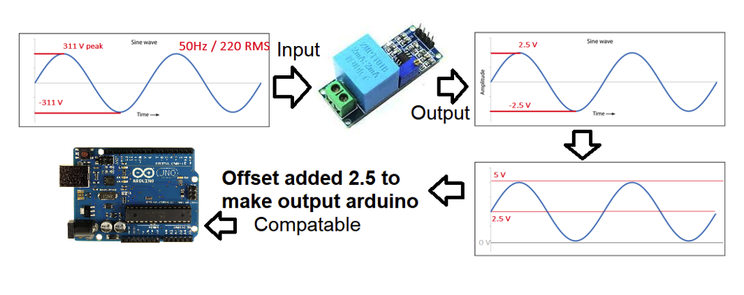
These transformers are typically big and bulky, so this do-it-yourself (DIY) project will incorporate one at a reduced size that can be easily interfaced with a microcontroller. The one used in this tutorial is the ZMPT101B. It’s a single phase with input peak-to-peak ratings of 311 and an output peak-to-peak of 2.5, which is a 0-5V range.

Potential transformers (PTs) are inserted in parallel in the main line. Their construction is similar to any other conventional transformer, except that PT’s only transform voltage from high to low (they’re also called a step-down transformer). This allows a voltage to be read by an external system that calculates the main voltage, power, etc.

The system flow is shown here:

A few points to note…

  • The sensor requires calibration before use. This can be done in the circuit or by rotating the potentiometer knob. Rotating the knob adjusts the resistance.
  • The transformer’s output must be divided using a voltage divider.
  • The resistance values can easily be calculated as we know the maximum input and output peak voltages.
  • The circuit’s internal calibration requires knowledge of the hardware and software. Using a predefined library for the PT sensor is a great resource to help.

This is the circuit of the Arduino PT sensor:

For simplicity, we’re using the DIY PT library. As such, the calibration function is predefined, so we’re off the hook when it comes to calculating it. Reading and translating the voltage is also simplified by defining it as a single function. Then, a user simply needs to call the function from his or her code.
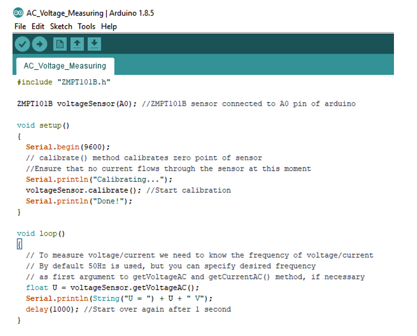
The project code:

Instructions

  • First, we imported the ZMPT101B potential transformer header file into the code.
  • Next, Arduino’s analog pin0 is declared as the input pin for Arduino.
  • In the setup function, the serial monitor is started at 9600bps.
  • The PT calibration function is called in the setup function.
  • In the loop/main function, the voltage is read every one second and printed on the serial monitor.
  • To view the main voltage, open the Arduino serial monitor at 9600bps.

Project circuit diagram:
The circuit diagram for this project is simple. The PT sensor module requires 5V to operate properly. We supplied this via Arduino’s 5V output.

Next, all you have to do is connect the PT output pins with Arduino’s analog pin0.

Now, it’s your turn to try this DIY project!

Where to buy the necessary parts?

  • Arduino: Mouser


Related Articles Read More >

How to monitor pH levels in an aquarium using Arduino
TV remote hack using Arduino and IR sensor
Gesture sensor using Arduino
How to build a metal detector using an inductive proximity sensor with Arduino

HAVE A QUESTION?

Have a technical question about an article or other engineering questions? Check out our engineering forums EDABoard.com and Electro-Tech-Online.com where you can get those questions asked and answered by your peers!


Featured Tutorials

  • Introduction to Wireless Modules
  • ADC with NRF24LE1 (Part 2/14)
  • Interrupts with NRF24LE1 (Part 3/14)
  • Power Failure Indicator in NRF24LE1 (Part 4/14)
  • Using EEPROM of NRF24LE1 (Part 5/14)
  • PWM with NRF24LE1 (Part 6/14)

Stay Up To Date

Newsletter Signup

EE Training Center Classrooms

“ee

“ee

“ee

“ee

“ee

Recent Articles

  • What are Application Specific ICs?
  • Introduction to LUFA
  • What are the different types of integrated circuits?
  • Introduction to Wireless Modules
  • ADC with NRF24LE1 (Part 2/14)

RSS EDABOARD.com Discussions

  • Inductive Current , High Current Track
  • Mains voltage range in India?
  • Thyristor choice?
  • Inspecting split AC control board not running the fan
  • Trying to repair an RF generator

RSS Electro-Tech-Online.com Discussions

  • Tesla coil progress
  • Two switch forward topology WEIRD waveform and efficiency issue
  • EasyEDA Discovery / Tip
  • Ideas for a homemade tv set?
  • How to breadboard with WSON devices.
Engineers Garage
  • Analog IC TIps
  • Connector Tips
  • DesignFast
  • EDABoard Forums
  • EE World Online
  • Electro-Tech-Online Forums
  • Microcontroller Tips
  • Power Electronic Tips
  • Sensor Tips
  • Test and Measurement Tips
  • 5G Technology World
  • About Us
  • Contact Us
  • Advertise

Copyright © 2021 WTWH Media LLC. All Rights Reserved. The material on this site may not be reproduced, distributed, transmitted, cached or otherwise used, except with the prior written permission of WTWH Media
Privacy Policy | Advertising | About Us

Search Engineers Garage

  • Projects and Tutorials
    • Circuit Design
    • Electronic Projects
      • 8051
      • Arduino
      • ARM
      • AVR
      • PIC
      • Raspberry pi
      • STM32
    • Tutorials
    • Components
  • Articles
    • Tech Articles
    • Insight
    • Invention Stories
    • How to
    • What Is
  • News
    • EE Design News
    • DIY Reviews
    • Guest Post
    • Sponsored Content
  • Forums
    • EDABoard.com
    • Electro-Tech-Online
    • EG Forum Archive
  • Digi-Key Store
    • Cables, Wires
    • Connectors, Interconnect
    • Discrete
    • Electromechanical
    • Embedded Computers
    • Enclosures, Hardware, Office
    • Integrated Circuits (ICs)
    • Isolators
    • LED/Optoelectronics
    • Passive
    • Power, Circuit Protection
    • Programmers
    • RF, Wireless
    • Semiconductors
    • Sensors, Transducers
    • Test Products
    • Tools
  • EE Resources
    • DesignFast
    • LEAP Awards
    • Oscilloscope Product Finder
    • Video
    • White Papers
    • Webinars
  • EE Learning Center
  • Women in Engineering