Pulse Width Modulation (PWM) is one of the five basic functionalities in any microcontroller. The other four are digital input, digital output, analog input, and serial data communication. Most microcontrollers do not have a built-in digital-to-analog converter to output analog signals. However, most of the microcontrollers have one or more PWM output interfaces. PWM signals are periodic rectangular signals with programmable ON and OFF pulse duration. With a modulated pulse width, these signals can approximate true analog output. PWM signals are not meant for analog data communication, delivering electrical power, or working with analog circuits. However, these signals are very useful in providing output power to external components like LED lights and speakers. These signals can also be used as control signals for actuators like servo motors.
PWM signals are used to control devices instead of delivering power to them. The power output from a microcontroller GPIO is too small to drive any actuator or device practically. For example, the maximum current that ESP32 and ESP8266 boards can sink or source is only 40 mA, and the operating voltage is just 3.3V. External power amplifier circuits are required to drive components like speakers and buzzers with PWM signals.
What is Pulse Width Modulation?
Pulse Width Modulation changes the average power delivered from a signal by chopping the square wave signal into discrete parts. It is not an actual continuous signal. Instead, a periodic digital signal’s ON, and OFF duration is modulated to reduce the effective voltage/power output. For example, if a microcontroller’s GPIO outputs 3.3V in digital output while generating a PWM signal of 50% duty cycle from the pin, it will output an effective voltage of approximately 1.65V, i.e., 3.3/2.
PWM vs. analog output
PWM signals are not true analog signals. True analog signals are continuous and can have any floating value. PWM signals are generated by dividing the output duration of digital signals by discrete values. Therefore, PWM signals can approximate expected analog outputs but can never have similar floating values. How close a PWM signal can approximate a floating-point value depends upon its resolution. For example, ESP8266 has a 10-bit PWM resolution with operating voltage at its GPIO being 3.3V. So, the voltages that the ESP8266 PWM controller can approximate will be in steps of 3.3/1023 V or 3.22 mV.
Also, note that PWM signals are periodic signals. They cannot approximate non-periodic continuous signals; even being periodic signals, PWM signals can not precisely approximate all frequencies. How close a PWM signal can match an output frequency depends on the base frequency of the microcontroller and the PWM resolution. For example, the base frequency in ESP32 can range from 1 Hz to 40 MHz, and PWM resolution can be set from 1 to 16 bits. Let it be set to 10 bits. Suppose you want to output a frequency of 300 KHz. If the base frequency is set to 40 MHz, the divider required for generating 300 KHz frequency will be 40,000,000/300,000, i.e., 133.33. If we use 133 as the divider, the actual signal frequency we obtained is 40,000,000/133, i.e., 300,751 Hz. This is not precisely 300 KHz.
Also, note that PWM output largely depends upon the particular behavior of the specific microcontroller/port. For example, Arduino boards use a dedicated hardware clock to generate PWM signals. The ESP boards use timers and interrupts for PWM generation, starting with a theoretical base frequency of 80 MHz. The PWM controller in ESP32 consists of two sub-modules – LED Control (LEDC) and Motor Control Pulse Width Modulator (MCPWM). In MicroPython, the Expressif’s IoT Development Framework (IDF) is used as the software development kit. The kit uses the same API for PWM implementation in ESP8266 and ESP32. In ESP32, the MicroPython firmware uses an LEDC peripheral for PWM generation. Arduino’s minimum and maximum frequencies depend only on the base clock frequency and the PWM resolution. But, in the case of ESP boards, it is dependent not only on hardware implementation like the base frequencies supported in Expressif’s IDF but also on software implementation in the MicroPython firmware. We will discuss this in detail later in this article.
MicroPython machine library
The machine module manages many hardware-related functions in MicroPython. This module consists of several classes that are written for controlling digital input/output, controlling output signals from external devices, pulse width modulation, analog to digital conversion, controlling ADC peripherals, UART, SPI, I2C, I2S, Timer, RTC, Watchdog timer, and manage SD card. The PWM controller is managed by the PWM class of the machine module.
MicroPython PWM class
The PWM class is written to provide pulse width modulation in MicroPython supported boards. This class can be imported into a MicroPython script using the following statements.
from machine import PWM
After importing, an object has to be instantiated from the PWM class. For this, machine.PWM() method is provided. This method has the following syntax.
class machine.PWM(dest, *, freq, duty_u16, duty_ns)
This construct returns a PWM object. The dest parameter is the PWM pin on which PWM output must be generated. This may be specified by a port-specific identifier that can be an integer, string, or a tuple depending upon the specific port. The freq, duty_u16, and duty_ns are optional parameters. The freq parameter is the frequency in Hz for the PWM cycle. The duty_u16 parameter specifies the duty cycle as ratio duty_cycle/65535. The duty_ns parameter specifies the pulse duration in nanoseconds. If the frequency is specified, either only duty_u16 or only duty_ns must be provided. Some of the valid examples of instantiating PWM objects are the following.
pwm0 = machine.PWM(Pin(0))
pwm0 = PWM(Pin(0))
pwm0 = PWM(Pin(0), 5000)
pwm0 = PWM(Pin(0), 5000, 2**16*1//2) //50% duty cycle
pwm0 = PWM(Pin(0), 5000, 250_000)
The class includes the following methods for configuring PWM output.
PWM.freq(): This method is used to get or set the current frequency of the PWM output. If called without arguments, it returns the frequency in Hz. A single integer argument can be passed to the method call for setting the frequency in Hz. The acceptable frequency range depends upon the specific microcontroller/port.
PWM.duty(): This method gets or sets the duty cycle as ratio duty_cycle/1023. If called without arguments, it returns the duty cycle as an unsigned integer value between 0 and 1023. An unsigned integer argument with a value of 0 to 1023 must be passed to set the duty cycle. For example, pwm0.duty(512) sets the duty cycle for PWM object pwm0 to 50%.
PWM.duty_u16(): This method gets or sets the duty cycle as the unsigned 16-bit value in the range from 0 to 65535. If called without arguments, it returns the duty cycle as an unsigned 16-bit number between 0 and 65535. An unsigned long argument with a value of 0 to 65535 must be passed to set the duty cycle.
PWM.duty_ns(): This method sets or gets the current pulse width of the PWM output in nanoseconds. When called without arguments, it returns the pulse width in nanoseconds. A value in the range from 0 to 1000,000,000 must be passed to set the pulse width.
PWM.init(*, freq, duty_u16, duty_ns): It modifies the configuration settings of the PWM object after the object is already constructed. It accepts the same parameters as the constructor object except for the PWM pin.
PWM.deinit(): This method disables the PWM object.
It is worth noting that frequency and duty cycle resolution are interdependent. Higher is the frequency, lower is the duty cycle resolution available.
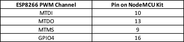
PWM in ESP8266
ESP8266 has four dedicated PWM output interfaces. These PWM interfaces are listed below.
MicroPython lets you specify a frequency range of 1 Hz to 1 KHz and a PWM resolution of 10 bits for ESP8266. In MicroPython, up to 8 PWM outputs can be run on ESP8266. Take a look at the following screenshot from esppwm.c in MicroPython firmware. In ESP8266, it is also possible to implement PWM by software. This involves the use of timer interruptions. The software PWM in ESP8266 can have a resolution as low as 44 nanoseconds. The PWM frequency range can be adjusted from 1 microsecond to 10000 microseconds, i.e., 100 Hz to 1KHz. The software PWM in ESP8266 allows a duty cycle resolution of 14 bits at a 1 KHz frequency. In ESP8266, PWM can be output on all GPIO except GPIO16.

Screenshot from MicroPython PWM module for ESP8266 port
For ESP8266, the PWM object can be instantiated using the machine.PWM() constructor. Note that the parameters duty_u16 or duty_ns are not acceptable for the ESP8266 port. The PWM frequency can be set or gotten using PWM.freq() method. The acceptable value for setting frequency is between 1 and 1000. The PWM duty cycle can be set or gotten using PWM.duty() method. The method accepts a 10-bit value as a parameter and sets the frequency as ratio duty_cycle/1023. Note that you cannot use duty_u16() or duty_ns() for setting or getting the duty cycle for ESP8266 as the board allows only 10-bit PWM resolution. A PWM object can be disabled by calling PWM.deinit() method.
PWM in ESP32
The PWM controller in ESP32 consists of two different sub-modules – LED Control (LEDC) and Motor Control Pulse Width Modulator (MCPWM). The MicroPython firmware uses only the LEDC module for PWM generation. This is evident from the following screenshot from ports/esp32/machine_pwm.c in MicroPython firmware.
Screenshot from MicroPython PWM module for ESP8266 port
There are 16 independent PWM channels in ESP32. These channels are divided into two groups — one group of eight high-speed channels and the other group of 8 low-speed channels. The PWM channels can be multiplexed to any GPIO except the input-only pins, i.e., GPIO34~39. For each group, there are four timers per eight channels. This means that each timer is coupled with two PWM channels. Therefore, only eight different PWM frequencies can be generated at a time from 16 PWM channels. However, it is possible to have different duty cycles on all 16 PWM channels. MicroPython lets use software PW to generate a different PWM frequency from 8 PWM channels.
The LEDC module of ESP32’s PWM controller can use one of three different source clocks listed below.
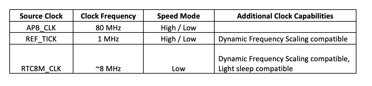
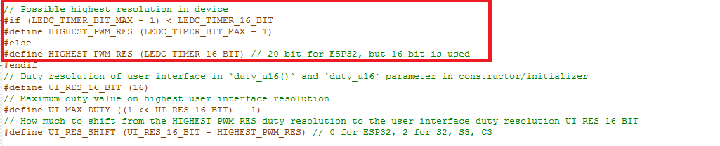
The MicroPython firmware utilizes only two clock sources APB_CLK and REF_TICK. If the frequency of a PWM object is set below 10 Hz, REF_CLK is used by the firmware; otherwise, APB_CLK is used as the clock source. Take a look at the following screenshot from ports/esp32/machine_pwm.c in MicroPython firmware.
![]()
The PWM frequency is also limited by the duty cycle resolution, apart from the clock source. Both PWM frequency and duty cycle resolution are inversely proportional. The higher the frequency, the lower the available duty cycle resolution.
Finally, the PWM resolution and duty cycle resolution are also limited by the PWM implementation of MicroPython. While the base clock APB_CLK used by Expressif’s IDF uses a theoretical frequency of 80 MHz, the maximum PWM frequency set for ESP32 is 40 MHz with a duty cycle resolution of 1 bit. This means that a 40 MHz PWM signal can be generated with a 50% or 100% duty cycle. The maximum PWM frequency that can be output with an 8-bit resolution is 312.5 KHz. The maximum PWM frequency that can be output with a 10-bit resolution is 78.125 KHz.
For ESP32, MicroPython allows you to specify PWM frequency from 1KHz to 40 MHz. The duty cycle resolution can be from 1 bit to 16 bits. To avoid any errors in PWM generation, first determine the desired duty cycle resolution. Higher will be the duty cycle resolution, more precisely, output voltage levels could be controlled. Once settled with a duty cycle resolution, you can calculate the highest possible PWM frequency using the following equation.
Max_PWM_freq = 80,000,000/2^Duty-Cycle-Resolution-Bit
For example, if we require a duty cycle resolution of 13 bits, the maximal PWM frequency will be as following.
Max_PWM_freq = 80,000,000/2^13
= 9.765 KHz
For ESP32, the PWM object can be instantiated using the machine.PWM() constructor. The duty cycle can be set using PWM.duty(), PWM.duty_u16() or PWM.duty_ns() methods. The PWM frequency can be set using PWM.freq() method. The PWM settings can be changed by calling PWM.init() method. The changes in PWM settings happen without CPU interruptions. The PWM object can be disabled by calling PWM.deinit() method.
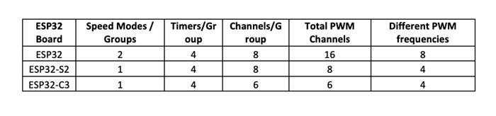
Note that some ESP32 boards have fewer PWM channels. The following table lists the PWM channels and their specifications for different ESP32 boards.
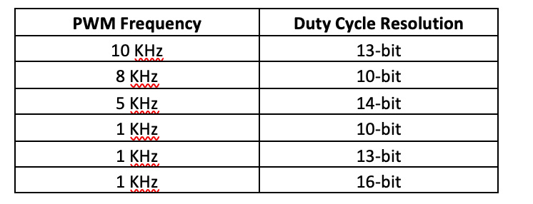
PWM applications
PWM signals are used for various applications like fading LEDs, dimming lights, controlling the direction of a servo motor, activating buzzers, controlling the speed of DC motors, generating audio signals from speakers, encoding messages for analog communication devices, and producing analog voltages. The following table lists some of the recommended PWM frequencies and duty cycle resolution for many common applications.
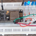
Fading LED on ESP8266 using MicroPython firmware
Fading LED lights is one of the typical applications of PWM signals. LED fading is often used to monitor the PWM output of a microcontroller. In this article, we will use MicroPython to fade LED on ESP8266.
Components required
- ESP8266 x1
- 5mm LED x1
- 330Ω resistor x1
- breadboard x1
- Connecting wires/Jumper wires
Circuit connections
Connect the anode of LED with GPIO14 of ESP8266 and its cathode to ground via a series resistor of 330 ohm. In this manner, the LED is connected with ESP32/ESP8266 such that it glows when the GPIO source current to the LED while it remains off until GPIO is at LOW logic.
Note that MicroPython firmware must be already uploaded in ESP8266. Learn about uploading MicroPython firmware in ESP8266 and ESP32.
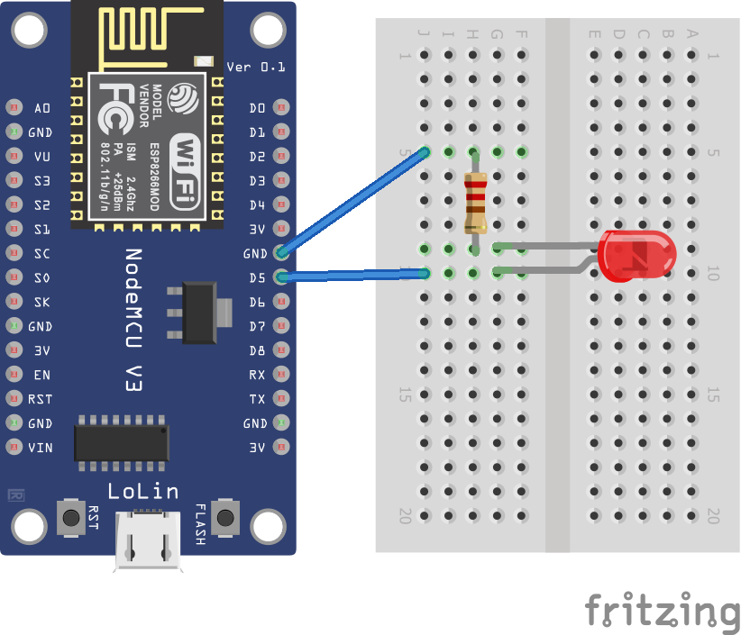
Circuit diagram for LED fading with ESP8266 using MicroPython PWM module
MicroPython script
from machine import Pin, PWM
from time import sleep
frequency = 1000
led = PWM(Pin(14), frequency)
while True:
for duty_cycle in range(0, 1024):
led.duty(duty_cycle)
sleep(0.005)
How it works
The LED is connected to ESP8266 such that it glows when the board source current to it. The ESP8266 delivers a PWM output to the LED. The PWM frequency is set to 1 KHz, which is the highest frequency available for ESP8266. The duty cycle can be adjusted at a resolution of 10 bits. So, the duty cycle is increased from 0 to 1023 at five-millisecond intervals. This gives a fading out and fading in effect over five seconds.
The code
The code begins with importing Pin and PWM classes from the machine and sleep classes from the time modules. The frequency is stored in a variable of 1000. A PWM object is instantiated by calling PWM() method. In an infinite while loop, the duty cycle is changed from 0 to 1023 and applied by calling PWM.duty() method for 5-millisecond intervals.
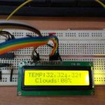
Results
You may also like:


Filed Under: Electronic Projects, ESP8266., Python, Tutorials

Questions related to this article?
👉Ask and discuss on EDAboard.com and Electro-Tech-Online.com forums.
Tell Us What You Think!!
You must be logged in to post a comment.