DDRB = BLINKER;
OLED_init(); // start displaying OLED
_delay_ms ( 10 );
OLED_floodfill(0xFF); // display OLED with bright light as self test
_delay_ms ( 500 );
ADC_init ( ); // initialize ADC system
OLED_floodfill(0x00); // blank display of OLED
_delay_ms ( 500 );
OLED_show_str_16x8 ( ” WELCOME TO “,6,0); // a welcome message
OLED_show_str_16x8 ( ” MINIATURE “,11,3); // is displayed on OLED
OLED_show_str_16x8 ( ” VOLT METER “,6,6); // as self test of text display on OLED
_delay_ms ( 1000 );
OLED_floodfill(0x00); // blank display of OLED
_delay_ms ( 300 );
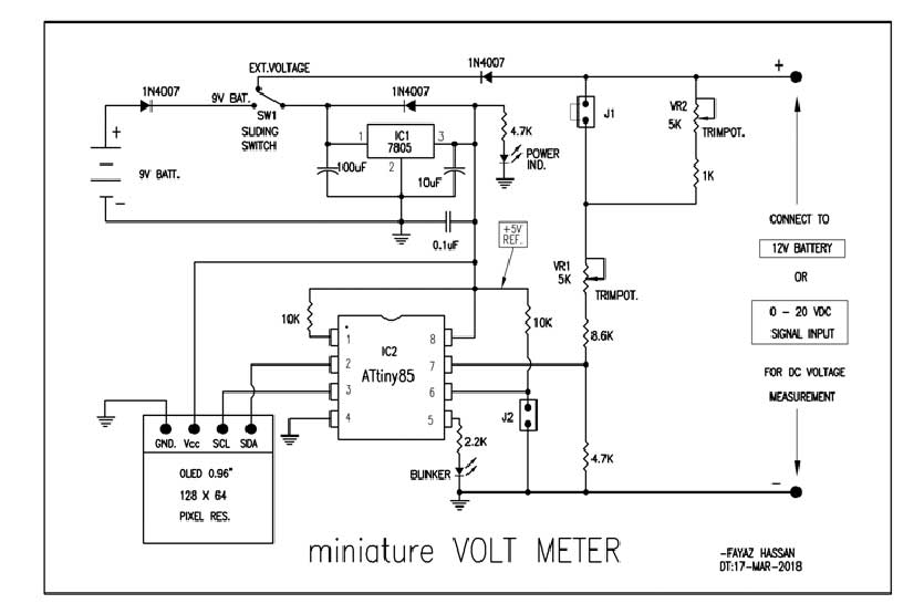
2) The user can take voltage reading of a standard (or known) voltage source and adjust the respective pot (as per the current battery mode) to calibrate the voltmeter. In this circuit, the voltmeter is calibrated using a standard 12V voltage source where ADC reading is adjusted to 900 (for 12V input) in 12V battery mode and 750 (for 12V input) in 20V battery mode. After calibration, the miniature voltmeter is expected to give exactly accurate voltage readings.
PORTB ^= BLINKER;                         // toggle blinker to indicate MCU is working
A = readAdc ( 1 );                               // read ADC value from channel no 1
curr_mode = (PINB & BATT12V);  // check the mode of operation by usage of jumper J2
// for 12V battery mode or 20VDC voltmeter
if ( prev_mode != curr_mode )
{
OLED_floodfill(0x00);
_delay_ms ( 50 );
}
if ( curr_mode>0 )
V = A/6;
else
V = A/5;
if ( curr_mode>0 )        // in case of 12V battery mode, appropriate status is diplayed on OLED
{
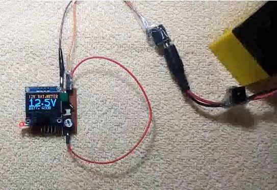
OLED_show_str_16x8 ( "12V BAT.METER",0, 0);
if ( V>150 )
OLED_show_str_16x8 ( "NOT 12V BAT  " , 0 ,6);
else if ( V>135 )
OLED_show_str_16x8 ( "OVER CHARG   " , 0 ,6);
else if ( V>120 )
OLED_show_str_16x8 ( "BATT. GOOD   " , 0 ,6);
else if ( V>100 )
OLED_show_str_16x8 ( "BATT. LOW    " , 0 ,6);
else if ( V>90 )
OLED_show_str_16x8 ( "BATT. WEAK   " , 0 ,6);
else if ( V>60 )
OLED_show_str_16x8 ( "BATT. DEAD   " , 0 ,6);
else //if ( V<30 )
OLED_show_str_16x8 ( "BATT.ABSENT  " , 0 ,6);
}
dispstr[0]=V/100+'0';
V=V%100;
dispstr[1]=V/10+'0';
dispstr[2]='.';
dispstr[3]=V%10+'0';
dispstr[4]='/';
dispstr[5]=0;
if ( A>1000 )      // in case the ADC read value is out of range then display as OVERFLOW
{
OLED_show_str_16x8 ( " OVERFLOW  " , 0 ,0);
_delay_ms ( 150 );
OLED_show_str_16x8 ( "" , 0 ,0);
_delay_ms ( 100 );
}
You may also like:
Project Source Code
/* Filename : miniVoltMeter.C author : Fayaz Hassan Date : 15-02-2018 MCU : ATtiny85 (A) Display : OLED (I2C) */ #define F_CPU 1000000UL #include#include #include #include "OLED_LIB.C" #define BLINKER 0b00000001 #define BATT12V 0B00000010 //======================================================================================== void ADC_init ( ) { ADCSRA |= ( (1 << ADPS2) | (1 << ADPS1) | (1 << ADPS0) | (1 << ADEN) ); } //======================================================================================== int readAdc ( int channelno ) { ADMUX = (channelno%4); ADCSRA |= (1 << ADSC); while (ADCSRA & (1 << ADSC)); return ADC; } //======================================================================================== int main ( ) { int V=0; int A=0; int prev_mode = -1; int curr_mode = 0; char dispstr[6]={'0','0','.','0','/',0}; _delay_ms ( 500 ); DDRB = BLINKER; OLED_init(); _delay_ms ( 10 ); OLED_floodfill(0xFF); _delay_ms ( 500 ); ADC_init ( ); OLED_floodfill(0x00); _delay_ms ( 500 ); OLED_show_str_16x8 ( " WELCOME TO ",6,0); OLED_show_str_16x8 ( " MINIATURE ",11,3); OLED_show_str_16x8 ( " VOLT METER ",6,6); _delay_ms ( 1000 ); OLED_floodfill(0x00); _delay_ms ( 300 ); readAdc ( 1 ); readAdc ( 1 ); while ( 1 ) { PORTB ^= BLINKER; A = readAdc ( 1 ); curr_mode = (PINB & BATT12V); if ( prev_mode != curr_mode ) { OLED_floodfill(0x00); _delay_ms ( 50 ); } if ( curr_mode>0 ) V = A/6; else V = A/5; if ( curr_mode>0 ) { OLED_show_str_16x8 ( "12V BAT.METER",0, 0); if ( V>150 ) OLED_show_str_16x8 ( "NOT 12V BAT " , 0 ,6); else if ( V>135 ) OLED_show_str_16x8 ( "OVER CHARG " , 0 ,6); else if ( V>120 ) OLED_show_str_16x8 ( "BATT. GOOD " , 0 ,6); else if ( V>100 ) OLED_show_str_16x8 ( "BATT. LOW " , 0 ,6); else if ( V>90 ) OLED_show_str_16x8 ( "BATT. WEAK " , 0 ,6); else if ( V>60 ) LED_show_str_16x8 ( "BATT. DEAD " , 0 ,6); else //if ( V<30 ) OLED_show_str_16x8 ( "BATT.ABSENT " , 0 ,6); } else { OLED_show_str_16x8 ( " VOLT METER " ,4, 0); OLED_show_str_16x8 ( "0-20 DC VOLTS" ,0 ,6); } dispstr[0]=V/100+'0'; V=V%100; dispstr[1]=V/10+'0'; dispstr[2]='.'; dispstr[3]=V%10+'0'; dispstr[4]='/'; dispstr[5]=0; if ( dispstr[0]=='0' ) dispstr[0] = ':'; OLED_show_str_32x24 ( dispstr , 5, 0,2); if ( A>1000 ) { OLED_show_str_16x8 ( " OVERFLOW " , 0 ,0); _delay_ms ( 150 ); OLED_show_str_16x8 ( " " , 0 ,0); _delay_ms ( 100 ); } prev_mode = curr_mode; } return 0; }
Circuit Diagrams
Project Video
Filed Under: Electronic Projects
Filed Under: Electronic Projects



Questions related to this article?
👉Ask and discuss on EDAboard.com and Electro-Tech-Online.com forums.
Tell Us What You Think!!
You must be logged in to post a comment.