Requirements:
- DTMF decoder
- 3.5mm audio cable (for connecting mobile to DTMF module)
- AT89S52
- 7805
- Geared dc motors
- Battery (10-12 v)
- 11.0592MHz crystal
- L293D IC (motor driver)
- Wheel for motors
Fig. 1: Image showing back side of 8051 Microcontroller based Mobile operated Robot

Fig. 2: Image showing top view of 8051 Microcontroller based Mobile operated Robot

Fig. 3: Image showing front side of 8051 Microcontroller based Mobile operated Robot

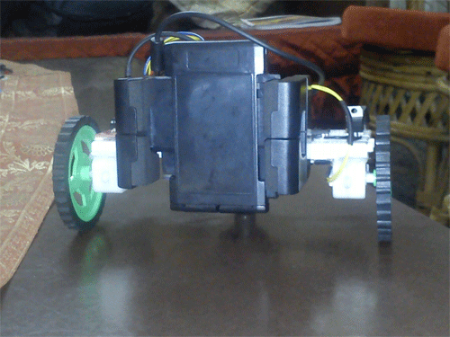
Fig. 4: Image showing side view of 8051 Microcontroller based Mobile operated Robot
Description:
Mobile controlling is done mainly with DTMF decoder. DTMF stands for Dual Tone Multi Frequency. This module can take up-to 4 bits of data at a time (i.e. 0-15 decimal values).
DTMF needs two mobile platforms, one for sending instructions while another for receiving them.
This module contains a IC which decodes the signals received and convert it into 4 bit data.
When you press the buttons on the keypad, a connection is made that generates two tones at the same time.

Fig. 5: Image showing key mapping of DTMF frequencies for a numeric keypad
generate the tones 1336 Hz and 697 Hz. Sure, the tone 697 is the same for both digits, but it take two tones toWhen you press the digit 1 on the keypad, you generate the tones 1209 Hz and 697 Hz. Pressing the digit 2 will
make a digit and the decoding equipment knows the difference between the 1209 Hz that would complete the digit
1, and a 1336 Hz that completes a digit 2.
This table shows the 4bit data output(bit by bit) from the DTMF decoder module according to the button pressed:

Fig. 6: Table listing frequencies and respective digital output used in DTMF
In this project I have used only 5 keys; they are:
2 (for forward movement)
4 (for moving left) 5 (for stopping the bot) 6 (for moving right)
8 (for backward movement)
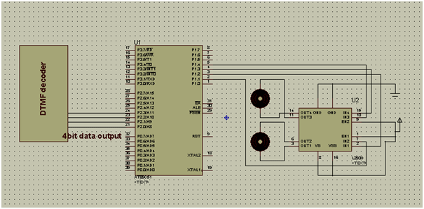
A particular DTMF module consists of signal pins (input signals from mobile via 3.5 mm jack), 4 pins (D0, D1, D2, D3,) for transmitting 4 bit data and one DV pin which becomes high on every successful data decoding.
In this project my DTMF 4bit pins are connected to PORT2 of MC (1.e. pin P2^0, 1, 2, 3).
The L293D inputs are connected to pin P1^1,2,3,4 respectively.
L293D will help us to drive DC geared motors perfectly.
In the coding part I have used a user defined header file L293D.h for controlling L293D acoording to the DTMF inputs.
You may also like:
Project Source Code
### Coding (MAIN): #include#include void main() { P2=0xff; stop(); while(1) { if(P2==0xf2) { forward(); while(P2==0xf2); } if(P2==0xf4) { left(); while(P2==0xf4); } if(P2==0xf5) { stop(); while(P2==0xf5); } if(P2==0xf6) { right(); while(P2==0xf6); } if(P2==0xf8) { backward(); while(P2==0xf8); } } } Coding (L293D): sbit MRp=P1^4; sbit MRn=P1^3; sbit MLp=P1^2; sbit MLn=P1^1; void forward() { MRp=1; MRn=0; MLp=1; MLn=0; } void backward() { MRp=0; MRn=1; MLp=0; MLn=1; } void left() { MRp=1; MRn=0; MLp=0; MLn=1; } void right() { MRp=0; MRn=1; MLp=1; MLn=0; } void stop() { MRp=0; MRn=0; MLp=0; MLn=0; } ###
Circuit Diagrams
Project Video
Filed Under: Electronic Projects
Filed Under: Electronic Projects





Questions related to this article?
👉Ask and discuss on EDAboard.com and Electro-Tech-Online.com forums.
Tell Us What You Think!!
You must be logged in to post a comment.