This is a complete different application from any other applications you have seen till yet.
With this unit you can activate or deactivate any application/device with the use of password only. Means to activate any device/application first you need to enter correct password. If you don’t device won’t be activated. you must have seen such type of application. This is a security related application. You can protect your personal or important devices from unauthentic persons.
As the name suggests it’s a multi digit and wireless password lock. So you can vary the length of password maximum up to 15 digits (this is because we are using 16 keys in remote control one key is used as Enter key) and also you can lock or unlock the device/application from remote place because it’s a wireless. LCD is just used to display messages.
Wireless keypad:-
Remote control used is same but now its role is changed. Now it will be used as remote keypad to enter password. Out of 16 keys 15 are used as password digits (say 0 to 9, A, B, C, D and E). Last key is used as Enter key to enter the password. Remote control will generate and transmit a special code for every digit you press. After pressing all password digits press Enter key.
Receiving unit:-
The figure given in circuit diagram tab.
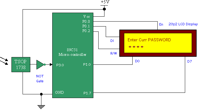
Connections:- There are only four components in the circuit IR sensor (TSOP 1738), NOT Gate IC 74LS04, microcontroller 89C51 and LCD display.
The inverted o/p of IR sensor is given to RXD (P3.0) pin of microcontroller. The data lines of LCD (D0-D7) are connected to port P1 of micro-controller. Control signals (R/W, DI, En) for LCD are generated by port P0 pins (P0.1,2 & 3).
Operation:- IR sensor will extract the code from modulated signal and gives it to microcontroller
Micro-controller works as serial data receiver. Whenever it gets any code it will store it in memory location. It will store all the received data bytes in consecutive memory locations. When you press enter switch from remote control, micro controller will start comparing received data bytes with the password stored in it. After byte by byte comparison if received bytes matches with all stored password bytes then lock is open, otherwise if any byte doesn’t match lock remains closed. Means you cannot activate the device/application to which this unit is attached.
LCD is used to display messages. As shown in figure it will continuously display “Enter curr PASSWORD” in its first line. When you press any key on remote it will display ” *” for each digit entered. After you press enter key comparison process starts. If you entered a correct password then in the second line a message is displayed “Correct PASSWORD” or if not then message will be “Wrong PASSWORD'” .
Circuit Diagrams
Filed Under: Electronic Projects


Questions related to this article?
👉Ask and discuss on EDAboard.com and Electro-Tech-Online.com forums.
Tell Us What You Think!!
You must be logged in to post a comment.