This circuit will light up different LED's according to the audio signals which are feed through condenser microphone. When sound intensity is low few LED's will glow as intensity of sound increases number of LED's which glow also increases. Important feature of this circuit is we have not use any special running light IC like LB1405. We have made this circuit with the help of seven channel Darlington array IC ULN2003. ULN2003 is a monolithic high voltage and current Darlington transistor array.
It contains seven NPN Darlington pair on a single IC. It also have high output voltage with common cathode clamp diode for switching inductive load. And collector current rating of each Darlington pair is 500mA. Another feature of ULN2003 IC it has 2.7kW series base resistor for each Darlington pair so that it can directly connected to TTL or 5V CMOS device. Read more to find out how this circuit is assembled and how it is made to work.
This music operated LED circuit will light up different LED’s according to the audio signals which are feed through condenser microphone. When sound intensity is low few LED’s will glow as intensity of sound increases number of LED’s which glow also increases. Important feature of this circuit is we have not use any special running light IC like LB1405. We have made this circuit with the help of seven channel Darlington array IC ULN2003.
Following components are used in this circuit-
1. ULN2003 IC – ULN2003 is a monolithic high voltage and current Darlington transistor array. It contains seven NPN Darlington pair on a single IC. It also have high output voltage with common cathode clamp diode for switching inductive load. And collector current rating of each Darlington pair is 500mA. Another feature of ULN2003 IC it has 2.7kW series base resistor for each Darlington pair so that it can directly connected to TTL or 5V CMOS device.
2. Zener diode – It allows current to flow in forward direction as same as normal diode, but it also allows current to flow in reverse direction when voltage above a certain value known as breakdown voltage is reached.
3. LED – LED stands for light emitting diode. It is made up of semiconductor device which emit different light source as its output. LED is a semiconductor diode that emits narrow-spectrum light when electrically biased in the forward direction of the p-n junction. When LED is switch on in this electronics combines with hole and the device release energy in the form of light. LED are Available in Red Orange Amber Yellow Green Blue White. Now a day’s LED’s are available in visible, ultraviolet and infrared wavelengths and have high brightness.
4. Resistor – Resistor is a two terminal passive component used to control the flow of current into the circuit. A current through resistor is directly proportional to the voltage applied across resistor terminal.
Resistor comes in two varieties –
a. Fixed resistor means they have fixed value of resistance.
b. Variable resistors means there value can be changed like if you have variable resistor of 5K then you can vary the resistance from 0 to 5 K Ohms.
We can calculate the value of resistor with the help of multimeter or we can do it with help of color code available on resistor.
5. Capacitor – A capacitor is a two terminal passive component which stores electric charge. Capacitors consist of two conductors which are separated by a dielectric medium. It works when potential difference applied across the conductors polarizes the dipole ions to store the charge in the dielectric medium.
Capacitor comes in two varieties-
1. Polarised capacitor- They have polarity means + and – sign. They are basically used to store charge. As they store charge they should be carefully discharge before troubleshooting the circuit.
2. Non polarised capacitor – They does not have polarity and can be mounted any way. They are basically used to remove the fluctuation present in conversion of AC to DC.
Working of circuit
When power supply is provided and music is played in front of Mic, capacitor C1 is used to feed the signals which are then rectified by Diode D1 and D2. Now zener diode has a feature that when breakdown voltage reaches diode starts conducting. In this circuit we are utilizing this feature; we have used different zener diode having different breakdown voltage and when sound intensity increases zener diode start conducting. At low volume zener diode have low breakdown voltage will conduct first and LED1 will glow. And when sound intensity increases other diodes also start conducting. And you will see different LED’s start glowing. You can use zener diode of other values also if the values mentioned in circuit diagram is not available. And you can vary the sound intensity with the help of VR1
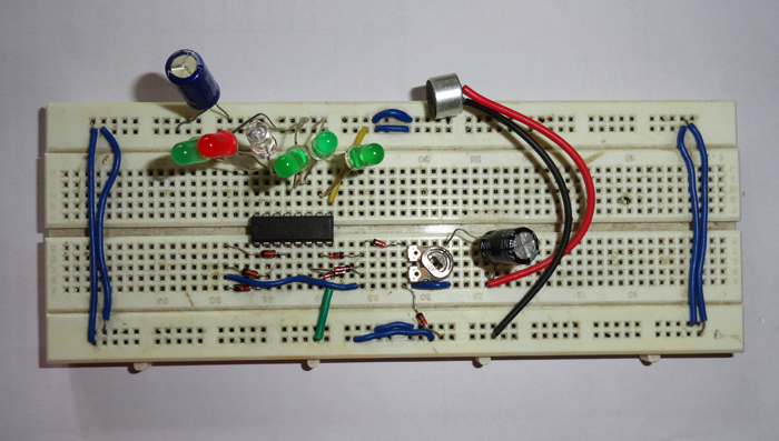
Fig. 1: Prototype of ULN2003 IC based Music operated LEDs
Circuit Diagrams
Project Components
Filed Under: Electronic Projects

Questions related to this article?
👉Ask and discuss on EDAboard.com and Electro-Tech-Online.com forums.
Tell Us What You Think!!
You must be logged in to post a comment.