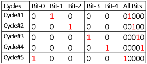
Ring counter exampleIn the below figure the size of the variable is fixed which is 5 bits. We want to revolve a fixed single-bit in 5 bit variable. Initially bit-1 is 1. In the next clock cycle the 1 is moved or shifted to bit-2 position and bit-1 is replaced with 0. This whole process shifts the 1 to next bit on each successive clock cycle. This movement of the 1 is also know as shifting.
|

N-bit ring counter in vhdl
N-bit counter tested on 4-bits

Ring counter vhdl code
In the process block the statement
Clk = ‘1’ AND Clk’EVENT checks if the positive edge of the clock is arrived. If arrived the control moves in the if statement and checks the next condition Rst=’1′. This statement means if reset is 1 then Currstate <= (0 => ‘1’,OTHERS =>’0′) which assigns Currstate=”1000″. So the system is reset and Currstate value is “1000”. If the reset is not 1 then the control jumps to ELSIF(En=’1′) statement. This statement checks if enable is active. If so Nextstate value is assigned to Currstate.The process ends up here. The next two statements are the real brain of the whole logic. The first statement picks the bit-0 of currstate and concatenate it with the rest. Then assign it to the nextstate.
What happens is on reset the currstate is 1000 as explained above. The next state is 0100 by the statement Nextstate <= Currstate(0) & Currstate(N-1 DOWNTO 1). & is a concatinate operator. This nextstate is assigned to currstate in the next clock cycle in which enable is activated and reset is disabled.
Finally the output is assigned the Currstate output <= Currstate;. Ring counter top level entity is shown in the figure below. The final RT level architecture is composed of four flip flops. The RT level architecture is not shown because the figure was occupying two much space and its hard to clearly see the RT components in the figure.
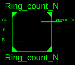
Ring counter top level entity
|
Ring counter vhdl test bench
Filed Under: Microcontroller Projects, VHDL

Questions related to this article?
👉Ask and discuss on Electro-Tech-Online.com and EDAboard.com forums.
Tell Us What You Think!!
You must be logged in to post a comment.