Introduction

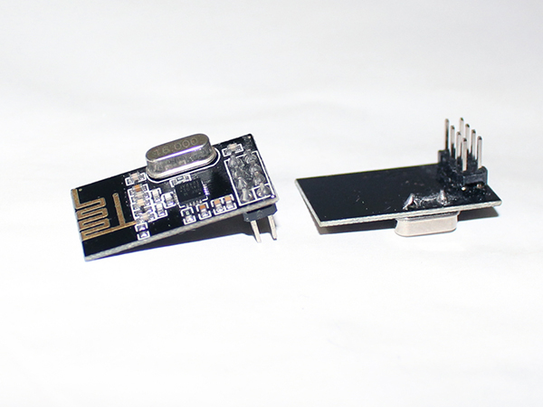
The nRF24L01 is a very inexpensive transceiver that runs in the 2.4 GHz space. It provides a true ultra-low power solution enabling months to years of battery life from a coin cell or AA/AAA batteries.
The Nordic nRF24L01+ integrates a complete 2.4GHz RF transceiver, RF synthesizer, and baseband logic including the Enhanced ShockBurst™ hardware protocol accelerator supporting a high-speed SPI interface for the application controller. No external loop filter, resonators, or VCO varactor diodes are required, only a low cost ±60ppm crystal, matching circuitry, and antenna.
It has following features:
· Highly integrated
· Ultra-low power 2Mbps RF transceiver IC for 2.4GHz band
· Worldwide license-free 2.4GHz ISM (industrial, scientific and medical) band operation
· 250kbps, 1Mbps, 2Mbps on-air-data-rate operations
· Enhanced ShockBurst™ hardware protocol accelerator
It can be used in various applications such as:
· PC peripherals
· Gaming
· Sports and fitness
· Toys
· Consumer electronics
Datasheet
You can find product data sheet at:
You don’t have to, but if you want to understand more about what you can do with this “little” radio, download the data sheet. In particular you may want to read pages 7-8-9 ( For Overview and Features), and page 39 (MultiCeiver, which allows 6 Arduinos to talk to a Primary Arduino in an organized manner). Fortunately the board-level products we have take care of many of the physical and electrical details and Antenna Impedance Matching etc., and this library takes care of lots of register initialization and operational details.
Note: Many users have had troubles getting the nRF24L01 module to work. It’s primarily because of the power it needs to work properly. This module works between 1.9 to 3.6 voltage ranges. Remember that while connecting this to your arduino board always use 3.3V pin. But sometimes (especially on Arduino Mega 2560 that has only 50mA of 3.3V) 3.3V power to the module does not have enough current capability or current surges causes problems. You can fix this problem easily by connecting 3.3uF to 10uF (micro-Farad) capacitor directly on the module from VCC to GND (pin 1 and pin 2). Some people say 10uF or larger.

[header= Arduino]
Arduino Library
There are number of libraries available for these modules:
http://playground.arduino.cc/InterfacingWithHardware/Nrf24L01
But we are going to use RF24by Maniacbug.
https://github.com/maniacbug/RF24
Once you’ve downloaded the library extract it, in that folder you’ll see a folder called RF24-master.ZIP, change the name of this file to just RF24. Open that folder and you will see another RF24-master. Rename this to just RF24 as well. Copy this folder and place it in your Arduino IDE libraries folder (C:Program Files (x86)Arduinolibraries). If you don’t find this folder just create a new folder with this name and paste your library here. Now you are good to go.
Experiment:
In this experiment we are going to send some random values wirelessly from one Arduino along with nRF24L01 to another Arduino board.
Hardware
· 2 x Arduino Uno
· 2 x nRF24L01
· Jumper wires (male to male)
· Jumper wires (female to female)

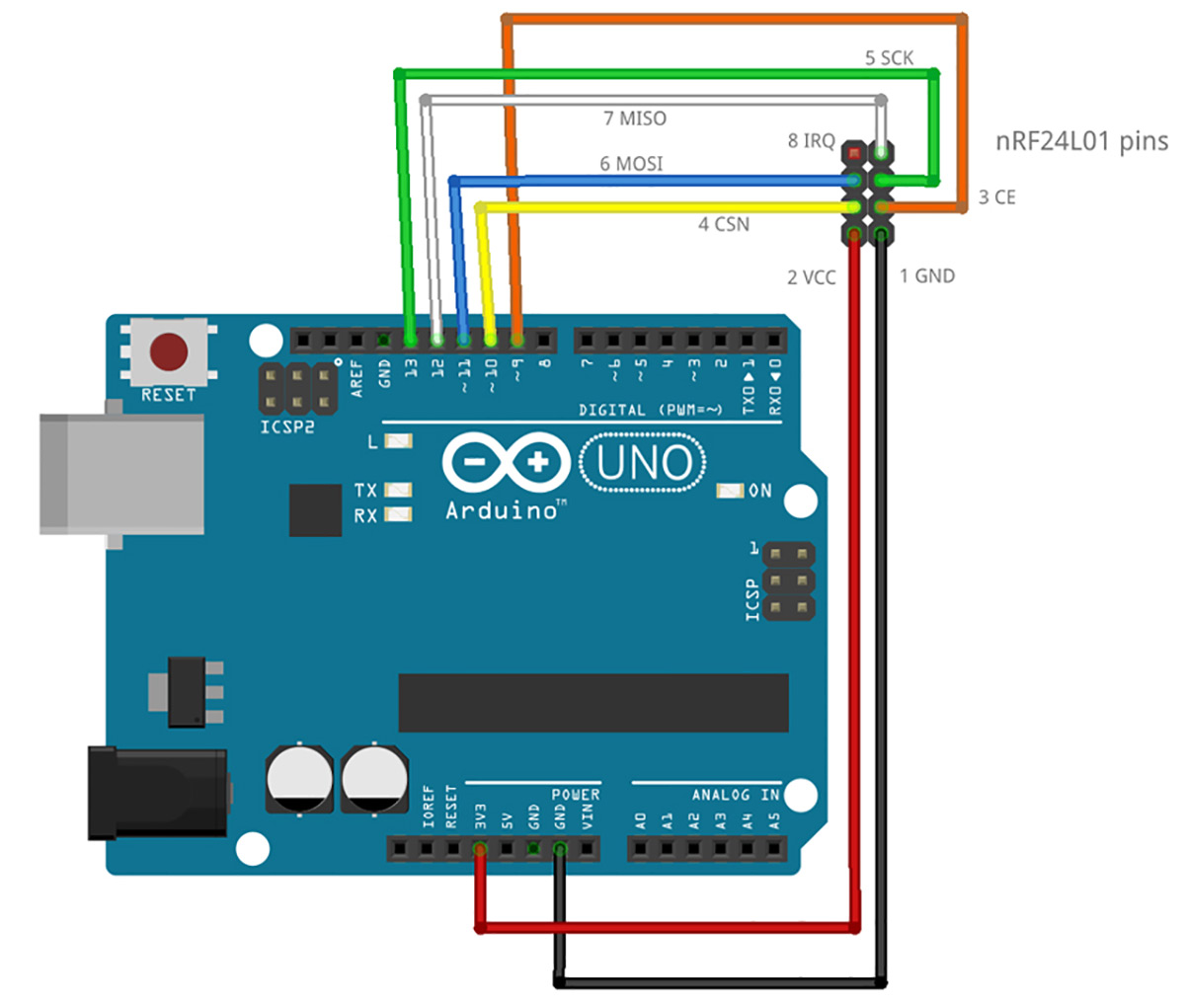
nRF24L01 connect on the SPI pins of your board. These pins are same on most of the Arduino boards except Arduino Mega. You can find more detail about SPI here:
http://www.arduino.cc/en/Reference/SPI
It will look something like this.
Result
Once the codes are uploaded open the serial monitor on the receiver side arduino IDE and
 you will see something like this.
Project Source Code
Project Source Code
###
#include <SPI.h>
/* Include RF24 library we donwloaded from Maniacbug */
#include <RF24.h>
#include <nRF24L01.h>
/* Declare constant and pin numbers, it is not necessary
buti like to do this because code is easily readable and
looks nice. */
#define CE_PIN 9
#define CSN_PIN 10
/* This is the pipe address we are going to use for our
communication, since we are doing 1 way communication we only need
one pipe. Note that LL at the end is LongLong data type. */
const uint64_t pipe = 0xE8E8F0F0E1LL; // Define transmit pipe
/* Declare radio object */
RF24 radio(CE_PIN, CSN_PIN); // create radio
/* Setup function runs once at the begining */
void setup() {
Serial.begin(9600); // start serial
radio.begin(); // initialize radio
/* since we are only transmitting data from this arduino
we will setup this as Writing. */
radio.openWritingPipe(pipe); // open writing pipe
}
/* Loop function runs continuosly. */
void loop() {
int message[2] = {}; // two element array to hold data
message[0] = 12;
message[1] = 34;
/* this function writes data over RF module to be sent wirelessly
this function also needs the size of data you are sending so that
it can be verified at the receiver end that receiver has obtained
complete data or not. */
radio.write(message, sizeof(message)); // transmit data to receiver
}
If you look at the code you will notice few commands like radio.openWritingPipe() that takes the pipe address argument this shows that this address will be used for writing. And module will write only when the writing pipe is open.
Receiver side:
/* We shall need SPI library as we are going to use
SPI pins SCK, MISO, MOSI for our RF module */
#include <SPI.h>
/* Include RF24 library we donwloaded from Maniacbug */
#include <nRF24L01.h>
#include <RF24.h>
/* Declare constant and pin numbers, it is not necessary
buti like to do this because code is easily readable and
looks nice. */
#define CE_PIN 9
#define CSN_PIN 10
/* This is the pipe address we are going to use for our
Communication.
Note that LL at the end is LongLong data type. */
const uint64_t pipe = 0xE8E8F0F0E1LL; // Define receive pipe
/* Declare radio object */
RF24 radio(CE_PIN, CSN_PIN); // create radio
/* Setup function runs once at the begining */
void setup() {
Serial.begin(9600); // start serial
radio.begin(); // initiate radio
radio.openReadingPipe(1,pipe); // start reading at pipe 1
radio.startListening(); // start listening
}
void loop() {
intreceived_message[2] = {};
if(radio.available()) { // check if the radio is available for communication
radio.read(received_message, sizeof(received_message)); // read incoming data
Serial.println(received_message[0]);
Serial.println(received_message[1]);
delay(1000);
} else { // if radio is not available print error message
Serial.println("No radio avaialable");
}
}
###
Circuit Diagrams
Filed Under: Electronic Projects


Questions related to this article?
👉Ask and discuss on EDAboard.com and Electro-Tech-Online.com forums.
Tell Us What You Think!!
You must be logged in to post a comment.