[[wysiwyg_imageupload:1996:]]Mr. Praveen Kumar from Chennai contributed this project report.
1.1.1 DEFINITION
1. A robot is an automatically guided machine, able to do tasks on its own.
2. Major classification of robot is industrial robot and service robot.
BLOCK DIAGRAM OF THE PROJECT

2.3 MEMORY UNIT :
The AT89C51 is normally shipped with the on-chip Flash memory array in the erased state (that is, contents = FFH) and ready to be programmed. The programming interface accepts either a high-voltage (12volt) or a lowvoltage (VCC) program enable signal. The low voltage programming mode provides a convenient way to program the AT89C51 inside the user’s system, while the high-voltage programming mode is compatible with conventional third party Flash or EPROM programmers. The AT89C51 is shipped with either the high-voltage or low-voltage programming mode enabled.
2.3.2 PROGRAMMING ALGORITHM:
- Input the desired memory location on the address lines.
- Input the appropriate data byte on the data lines.
- Activate the correct combination of control signals.
- Raise EA/VPP to 12 V for the high-voltage programming mode.
- Pulse ALE/PROG once to program a byte in the Flash array or the lock bits. The byte-write cycle is self-timed and typically takes no more than 1.5 ms. Repeat steps 1 through 5, changing the address and data for the entire array or until the end of the object file is reached. Data Polling: The AT89C51 features Data Polling to indicate the end of a write cycle. During a write cycle, an attempted read of the last byte written will result in the complement of the written datum on PO.7. Once the write cycle has been completed, true data are valid on all outputs, and the next cycle may begin. Data Polling may begin any time after a write cycle has been initiated.

- Clock up to 9 cycles.
- Look for SDA high in each cycle while SCL is high
- Create a start condition.

CHAPTER 3
HARDWARE REQUIREMENTS AND SOFTWARE REQUIREMENTS
 FIGURE 3.1CIRCUIT FOR 5V POWER SUPPLY


- TTL, DTL, PMOS, or CMOS-Compatible Inputs
- Output Current to 500 mA
- Output Voltage to 95 V
- Transient-Protected Outputs
- Dual In-Line Plastic Package or Small-Outline IC Package
3.4 OBSTACLE SENSING:

|
Development Tools
|
Supported Microcontrollers
|
Description
|
|
C51 Compiler,
A51 Macro Assembler, BL51 Linker/Locater |
Classic 8051 Devices.
|
Supports standard 8051 devices and includes support for 32 x 64K code banks.
|
|
C51 Compiler
(with OMF2 Output), AX51 Macro Assembler, LX51 Linker/Locater |
Classic 8051 Devices,
Extended 8051 Variants, Dallas 390/52xx/400/41x. |
Supports standard and extended 8051 devices. Includes support for code banking and up to 16MB code and xdata memory.
|
|
CX51 Compiler,
AX51 Macro Assembler, LX51 Extended Linker/Locater |
Philips 80C51MX Devices.
|
Supports Philips 80C51MX devices that provide a linear 16MB address space.
|
 FIGURE 3.9 8051 VARIANTS
3.6.4 8051-SPECIFIC OPTIMIZATION
The linker rearranges code segments to maximize AJMP and ACALL instructions which are shorter than LJMP and LCALL instructions.
Code involving switch and case statements is optimized using jump tables or jump strings.
Data and bit segments suitable for static overlay are identified and internally marked. The linker has the capability, through global data flow analysis, of selecting segments which can then be overlaid.
Variables from the IDATA, XDATA, PDATA and CODE areas are directly included in operations. Intermediate registers are frequently unnecessary.
Redundant MOV instructions are removed. This includes unnecessary loading of objects from the memory as well as load operations with constants. Complex operations are replaced by simple operations when memory space or execution time can be saved.
3.6.6 CREATING A NEW PROJECT
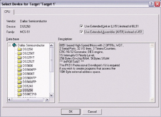 FIGURE 3.10 SELECTING THE DS5250 FOR A NEW KEIL µVISION2 PROJECT.
A new dialog box will ask, “Copy Dallas 80C390 Startup Code to Project Folder and Add File to Project?” Select YES.
Select the Target tab. Change the settings in this tab as follows (as shown below in Figure 4.3):
- Memory Model – Set to Large: Variables in XDATA.
- Code ROM Size – Set to Contiguous Mode: 16 MB program.
- Set the checkbox for Use multiple DPTR registers.
- In the Off-chip Code Memory section of the dialog, set the top two fields to Eprom Start: 0x1400 and Eprom Size: 0x10000.
- In the Off-chip Xdata Memory section of the dialog, set the top two fields to Ram Start: 0x80000 and Ram Size: 0x10000.
 FIGURE 3.11 TARGET OPTION DETTINGS FOR THE DS5250.
To compile the project, press F7, or select Project -> Build Target from the menu. If no errors occur, messages should appear indicating that compilation completed successfully, as shown in Figure 3.12. FIGURE 3.12 COMPILATION OUTPUT FROM KEIL µVISION
Before loading the compiled application on the DS52x0 Evaluation Kit board, the board should be set up as follows:
- A 6-9 volt DC power supply (center post positive) should be connected to power plug J1.
- A straight-through, DB9 serial cable should be connected from J3 (SERIAL 0) to COM1 on the host PC.
- A 22.1184 MHz crystal should be inserted.
- All DIP switches should be OFF except for A1-A4, B1, and B2 which should be ON.
- Open Microcontroller Tool Kit. In the microcontroller type dialog, select DS5240/50.
- Turn power on to the DS52x0 Evaluation Kit Board.
- Select Options -> Configure Serial Port. Set the serial port options to COM1 and 9600 baud.
- Select Target -> Open COM1 at 9600 baud (or hit Ctrl+O).
- Select Target -> Connect to Loader (or hit Ctrl+L).
- A loader prompt should appear (DS5250 SECURE LOADER…)
- At the loader prompt, type “W MSIZE 12” and hit ENTER.
- At the loader prompt, type “W MCON 81” and hit ENTER.
- Select File -> Load from the menu (or hit Ctrl+H). Select the compiled application hex file.
- Once loading completes, set the DIP switch B1 to the OFF position.
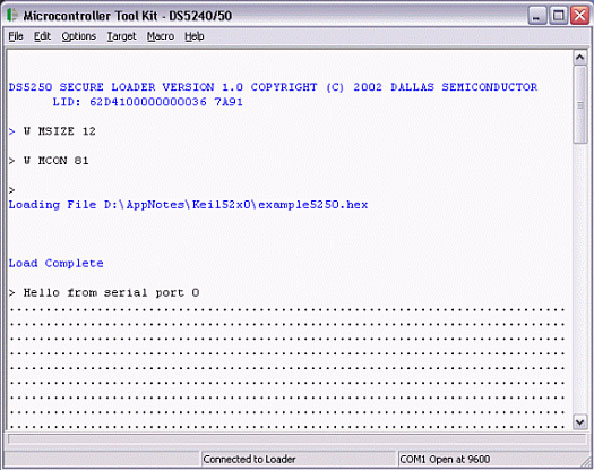 FIGURE 3.13 OUTPUT FROM MICROCONTROLLER TOOL KIT
OUTPUT AND RESULTS OF PROJECT


- Increase Efficiency
- Decrease Production Costs
- Improve Product Quality
- Are Ideal for Hazardous Conditions
- Coal mining
- Military Operation
- Fire fighting Operation
- Undersea Robots
- Garbage Collection and Waste Disposal Operations
Project Source Code
Project Source Code
###
#include <stdio.h>
#include <reg5240.h>
// Initialize serial port 0 to 9600 baud using 22.1184
MHz
crystal
void serialInit()
{
PCON |= 0x80;
SCON0 = 0x50;
TMOD |= 0x21;
TH1 = 0xDC;
CKCON |= 0x10;
TCON = 0x50;
SCON0 |= 0x02;
}
void main()
{
serialInit();
printf('Hello from serial port 0r');
while (1) {
P0 = 0x55;
printf(".");
P0 = 0xAA;
printf(".");
}
}
Save this file as main.c. The file will not be automatically added to the project. To add the file, right-click on Source
Group 1 and select Add Files to Group 'Source Group 1'. Select main.c and click Add, then click Close.
Next, open the file START390.A51 and comment out the following lines (after the STARTUP1 label):;
MOV
TA,#0xAA ; Enable access to P4CNT;
MOV TA,#0x55 ;
P4CNT_VAL EQU (SBCAN SHL 6) OR (PCES SHL 3) OR (P4PF);
MOV P4CNT,#P4CNT_VAL ;
; MOV TA,#0xAA ; Enable access to P5CNT;
MOV TA,#0x55
;P5CNT_VAL EQU (SP1EC SHL 5) OR (CX_IO SHL 3) OR (P5PF);
MOV P5CNT,#P5CNT_VAL
Also, change the line
#include <reg390.h>
to
#include <reg5240.h>
###
Filed Under: Electronic Projects

Questions related to this article?
👉Ask and discuss on Electro-Tech-Online.com and EDAboard.com forums.
Tell Us What You Think!!
You must be logged in to post a comment.