Engineers Garage

  • Projects and Tutorials
    • Electronic Projects
      • 8051
      • Arduino
      • ARM
      • AVR
      • PIC
      • Raspberry pi
      • STM32
    • Tutorials
    • Circuit Design
    • Project Videos
    • Components
  • Articles
    • Tech Articles
    • Insight
    • Invention Stories
    • How to
    • What Is
  • News
    • Electronic Products News
    • DIY Reviews
    • Guest Post
  • Forums
    • EDABoard.com
    • Electro-Tech-Online
    • EG Forum Archive
  • Digi-Key Store
    • Cables, Wires
    • Connectors, Interconnect
    • Discrete
    • Electromechanical
    • Embedded Computers
    • Enclosures, Hardware, Office
    • Integrated Circuits (ICs)
    • Isolators
    • LED/Optoelectronics
    • Passive
    • Power, Circuit Protection
    • Programmers
    • RF, Wireless
    • Semiconductors
    • Sensors, Transducers
    • Test Products
    • Tools
  • EE Resources
    • DesignFast
    • LEAP Awards
    • Oscilloscope Product Finder
    • White Papers
    • Webinars
  • EE Learning Center
  • Women in Engineering

Obstacle/Edge Detecting and Avoiding Vehicle

By Ajit Matthew


The aim of the project is to build a robot which, in simple terms, is a hand and edge detecting and avoiding vehicle. When our hand comes from the top, it avoids it by moving away. Further, it will not fall off the table edge.

BLOCK DIAGRAM:

Block Diagram of Obstacle Avoiding Robot

Fig. 1: Block Diagram of Obstacle Avoiding Robot

Circuit for Obstacle and Edge Detection Vehicle

The clockie consists of 4 basic modules:

i) IR Sensor Part

ii) LED & LDR Part

iii) Monostable Part

iv) Digital Logic & Motor Part

i) IR Sensor Part:

In this part, I use 2 pairs of IR LED and photodiode. I have used 2 of them for 2 reasons:

i) To detect hand coming from 2 directions

ii) To make the robot work in both day and night

During day, the photodiodes receive most of the IR radiation from the sun. So while hand comes during the day, it actually blocks the sunlight, thus reducing the amount of IR received by sensors. But during night, hand reflects the IR onto the diode.

These two are opposing behaviours. Hence to make the robot work throughout the day, I have used the XNOR logic. So when one of the sensors’ output differs from other’s the XNOR gate produces a logic low, which is used to trigger two monostables – MS1 (which decides the total time of operation of the circuit) and MS2(which causes the robot to move in the forward direction).

Circuit Diagram of IR Sensor Module

Fig. 2: Circuit Diagram of IR Sensor Module

ii) LED and LDR part:

In this part I have used 2 LED’s and 2 LDR’s and 2 comparators.

The LDRs are connected to 2 potentiometers basically for potential dividing and this potential is given to one of the comparators’ input and a reference voltage is given to the other input. I have fixed the reference so that the sensor works properly in day time as well as in the night time.

When the robot is on the table, the comparator output is logic 1(ldr receives maximum reflected light). When one of the sensors detects an edge (i.e. when ldr receives no light), the comparator output goes low. The output of both the comparators and the output of MS1 are ANDed and is given to the reset of MS2. This stops the forward motion and starts the backward motion.

The outputs of the comparators are stored in a flip-flop so that it saves the information as to which sensor has gone out of the table.

This is required because as soon as the robot moves backward, the comparator outputs become 1 again. Hence to decide the appropriate direction of turning, comparator outputs are saved.

Circuit Diagram of LDR Module

Fig. 3: Circuit Diagram of LDR Module


iii) Monostable Part:

Time for which monostable circuit using 555 gives a high pulse is given by:

TH  = 1.1RC

I have used 4 monostables:

a)                {C}{C}{C}{C}{C}{C}{C}{C}{C}{C}MS1 : Decides the total time of operation of the entire circuit. It is triggered when a hand comes(i.e. when IR sensor part gives a 1to 0 transition).

TH  = 22s

=  R = 1 Mohm , C = 22uF

b)MS2 : Makes the robot move in the forward direction. It is triggered when IR sensor part

gives a 1 to 0 transition as well as when the output of MS4 makes a transitionfrom 1 to 0.

TH  = 5s

=   R = 5 Mohm, C = 1uF

Hence if no edge comes in 5s, the robot will reverse and turn (just to make it interesting!!).

c)MS3 : Makes the robot move backwards. It is triggered when MS1 goes from high to low.

TH  = 0.33s

=   R = 330 kohm, C = 1 uF

d) MS4 : Makes the robot turn. It is triggered when MS3 goes low. It acts as the select input to the multiplexer in the module 4.

TH  = 0.33s

=   R = 330 kohm, C = 1 uF

As mentioned earlier, LDR sensor part gives reset to MS2. The reset of MS3 & MS4 are given from the IR sensor output. So if hand comes while Clockie is moving backwards or while turning, it changes the current motion(either back or turn) to forward motion(as MS2 is also triggered).

 iv) Digital Logic & Motor Part:

a) Flip Flop:

A J–K flip flop is used to store the information as to which sensor has gone out.

The truth table of the J–K flip flop is as follows

Circuit Diagram of Timer Section

Fig. 4: Circuit Diagram of Timer Section


J

(Noted o/p of sensor1)

K

(NOTed o/p of sensor2)


Q

(to MUX)

0

0

HOLD

0

1

RESET

1

0

SET

1

1

TOGGLE


When the Clockie is on the table, the flip–flop is in HOLD state. When one of the sensors go out of the table, either J or K is 1. Now when the robot comes back to the table, the flip– flop is in the HOLD state thus retaining the previous information.

b) 2–iput Multiplexer:

Select input is the output of MS4(say C). When C is low, the output of the MUX is A(output of MS2). When C is high, the MUX output should be decided by the flip–flop.

Hence the below configuration:
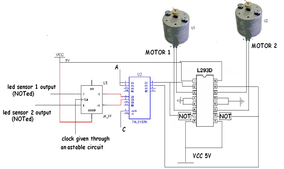
tiplexer


Fig. 5: 

c)  H–Bridge(L293D):

1A

1B

2A

2B

Action

1

0

1

0

Both forward

0

1

0

1

Both backward

1

0

0

1

Turn right

0

1

1

0

Turn left

The MUX output goes to the pins 2(1A) and 15(1B) of the h– bridge.

2A = (1A)’ and 2B = (1B)’

Hence the motors are driven. Motors used are D.C motors.

Working with sensors:

Sensors being environment dependant caused too much trouble. Everytime voltage references had to be changed. I tried my best to make it work throughout the day. So we used 2 IR sensors and made them work according to XOR logic. Moreover the photodiodes were covered.

Application:

Waking up early in the morning is very difficult to most of us. Hence to force you out of bed, Clockie is an expert. An alarm can be fixed on it. When you try to switch off the alarm to go back to sleep, the clockie avoids your hand and moves away. Also it makes sure that it wont fall off the table. So it forces you to get out of your bed and switch it off. Once you are out of your bed, you don’t (most of the time) feel like going back to bed(if you are really serious of waking up).

tiplexer

Fig. 6: Symbols of 2-Input Multiplexer

Circuit Diagrams

Circuit-Diagram-Obstacle-Avoiding-Robot


Filed Under: Electronic Projects
Tagged With: edge detection, obstacle avoidance, vehicle
 

Questions related to this article?
👉Ask and discuss on EDAboard.com and Electro-Tech-Online.com forums.


Tell Us What You Think!! Cancel reply

You must be logged in to post a comment.

HAVE A QUESTION?

Have a technical question about an article or other engineering questions? Check out our engineering forums EDABoard.com and Electro-Tech-Online.com where you can get those questions asked and answered by your peers!


Featured Tutorials

  • Designing Gate Driver Circuit and Switching Mechanism for Modified Sine Wave Inverter – (Part 9/17)
  • Completing Modified Sine Wave Inverter Design with Full Bridge Circuit and Step Up Transformer – (Part 10/17)
  • Designing an Offline UPS – Part (12 /17)
  • How to reduce Switching Time of a Relay – (Part 15/17)
  • Testing MOSFET – (Part 16/17)
  • Driving High Side MOSFET using Bootstrap Circuitry – (Part 17/17)

Stay Up To Date

Newsletter Signup

Sign up and receive our weekly newsletter for latest Tech articles, Electronics Projects, Tutorial series and other insightful tech content.

EE Training Center Classrooms

EE Classrooms

Recent Articles

  • MicroPython – I2C protocol in ESP8266 and ESP3
  • New automotive radar sensor enables reliable in-cabin monitoring system
  • TI breaks ground on 300-mm semiconductor wafer-fabrication plants in Texas
  • New wireless AR Smart Viewer reference design
  • Infineon launches scalable and wireless charging platform with configurable controllers

Most Popular

5G 555 timer circuit 8051 ai Arduino atmega16 automotive avr dc motor display Electronic Part Electronic Parts Fujitsu ic infineontechnologies integratedcircuit Intel IoT ir lcd ldr led maximintegratedproducts microchip microchiptechnology Microchip Technology microcontroller microcontrollers mosfet motor powermanagement Raspberry Pi remote renesaselectronics renesaselectronicscorporation Research samsung semiconductor sensor software STMicroelectronics switch Technology vishayintertechnology wireless

RSS EDABOARD.com Discussions

  • What's the deal with all these "MPPT" IC's with no current sense?
  • Photovoltaic MOSFET Drivers - Voltage Rating
  • Impedance requirement for SDRAM signals
  • A circuit that can adjust a resistance and probing a voltage node
  • A analogue circuit that spit out the resistance desired

RSS Electro-Tech-Online.com Discussions

  • IRS2453 the H circuit
  • Ampro 16mm Stylist projector woes.
  • How to quickly estimate lead acid battery capacity ?
  • Finally switched to Linux.
  • Multistage BJT amplifier
Engineers Garage
  • Analog IC TIps
  • Connector Tips
  • DesignFast
  • EDABoard Forums
  • EE World Online
  • Electro-Tech-Online Forums
  • Microcontroller Tips
  • Power Electronic Tips
  • Sensor Tips
  • Test and Measurement Tips
  • 5G Technology World
  • About Us
  • Contact Us
  • Advertise

Copyright © 2022 WTWH Media LLC. All Rights Reserved. The material on this site may not be reproduced, distributed, transmitted, cached or otherwise used, except with the prior written permission of WTWH Media
Privacy Policy | Advertising | About Us

Search Engineers Garage

  • Projects and Tutorials
    • Electronic Projects
      • 8051
      • Arduino
      • ARM
      • AVR
      • PIC
      • Raspberry pi
      • STM32
    • Tutorials
    • Circuit Design
    • Project Videos
    • Components
  • Articles
    • Tech Articles
    • Insight
    • Invention Stories
    • How to
    • What Is
  • News
    • Electronic Products News
    • DIY Reviews
    • Guest Post
  • Forums
    • EDABoard.com
    • Electro-Tech-Online
    • EG Forum Archive
  • Digi-Key Store
    • Cables, Wires
    • Connectors, Interconnect
    • Discrete
    • Electromechanical
    • Embedded Computers
    • Enclosures, Hardware, Office
    • Integrated Circuits (ICs)
    • Isolators
    • LED/Optoelectronics
    • Passive
    • Power, Circuit Protection
    • Programmers
    • RF, Wireless
    • Semiconductors
    • Sensors, Transducers
    • Test Products
    • Tools
  • EE Resources
    • DesignFast
    • LEAP Awards
    • Oscilloscope Product Finder
    • White Papers
    • Webinars
  • EE Learning Center
  • Women in Engineering