Op-amp 741 is a very well-known as well as very usable IC in many of the projects like amplifier circuits, voltage follower circuits, current to voltage changer or voltage to current changer and many more other applications. So for the proper working circuit it is highly necessary that your op-amp works correctly. So here the circuit that will help you to check whether your op-amp is in good condition or it is faulty.

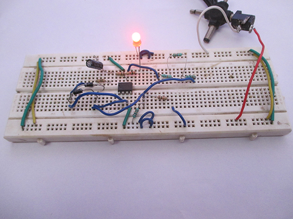
Fig. 1: Prototype of 741 OPAMP IC Tester
Summary of the circuit-
1. OP-amp tester is very easy and usable circuit.
2. With the help of this circuit you can check your op-amp 741 before connecting to any other circuit.
3. It is made with the help of few discrete components i.e. resistors, diodes, capacitors and LED.
4. It requires only 12V of DC power supply to carry out its work.
Principle behind Circuit-
Op-amp 741 is a very well-known as well as highly usable IC in many projects like amplifier circuits, voltage follower circuits, current to voltage changer or voltage to current changer and various other applications. So, for the proper working of circuit, it is really important that your op-amp works correctly. So here, the circuit will help you to check whether your op-amp is in good condition or it is faulty.
Op-amp 741 is a DC coupled IC having a large gain differential amplifier along with negative external feedback. It has about zero output impedance with just about infinite input impedance and approximately infinite open loop gain.
In this project, when you place the IC for checking and LED1 (red colour LED is used here you can used any colour you want) glows, this implies that your IC is in good state. But if the LED blinks (i.e. on and off) that shows that you IC is not in good condition and you need to change it.
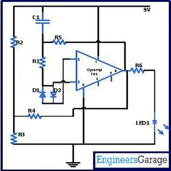
At the time when power supply of about 12V is given and IC 741 (which you want to test) is connected in the circuit, C1 capacitor slowly begins its charging with the help of resistor R5. Now when the charging of C1 just surpasses the potential present at the negative terminal, the Vout (output voltage) comes down. In this situation, C1 starts discharging and the chain of operation replicates. This generates square waves at the output stage and this is how LED1 glows for good IC.
Components required building the circuit-
IC
IC1 741
Resistor
R1, R2, R3, R5 10K
R4 5.6K
R6 1K
Capacitor
C1 10uF
LED
LED1 Any colour
Diode
D1, D1 1N4007
Power Supply 12V
Circuit Diagrams
Project Video
Filed Under: Circuit Design
Filed Under: Circuit Design


Questions related to this article?
👉Ask and discuss on EDAboard.com and Electro-Tech-Online.com forums.
Tell Us What You Think!!
You must be logged in to post a comment.