1.1 HISTORICAL PERSPECTIVE

Advantages of Optical Fiber
1.2 Advantages of optical fiber

Immunity to electromagnetic interference
Low attenuation loss over long distances
Classificaiton of Fiber Cables
Types of Optical Fibres
Different types of OPTICAL FIBERS
The following is a summary of the dominant optical fiber types with an indication of their general characteristics. The performance characteristics of the various fiber types discussed vary considerably depending upon the materials used in the fabrication process and the preparation technique involved. The values quoted are based upon both manufacturers’ and suppliers’ data, and practical descriptions for commercially available fibers, presented in a general form rather than for specific fibers. Hence in some cases the fibers may appear to have somewhat poorer performance characteristics than those stated for the equivalent fiber types produced by the best possible techniques and in the best possible conditions. It is interesting to note, however, that although the high performance values quoted were generally for fibers produced and tested in the laboratory, the performance characteristics of commercially available fibers in many cases are now quite close to these values. This factor is indicative of the improvements made over recent years in the fiber materials preparation and fabrication technologies.
This section therefore reflects the relative maturity of the technology associated with the production of both multi component and silica glass fibers. In particular, high performance silica-based fibers for operation in three major wavelength regions (0.8 to 0 9, 1.3 and 1.55/mm) are now widely commercially available. Moreover, complex refractive index profile single-mode fibers, including dispersion modified fibers and polarization maintaining fibers, are also commercially available and in the former case are starting to find system application within communications. Nevertheless, in this section we concentrate on the conventional circularly symmetric step index design, which remains at present the major single-mode fiber provision within telecommunications.
Multimode Step Index Fibers
MULTIMODE STEP INDEX FIBERS
Multimode step index fibers may be fabricated from either multi component glass -compounds or doped silica. These fibers can have reasonably large core diameters large numerical apertures to facilitate efficient coupling to incoherent light Structure
Numerical aperture: 0.16 to 0.5. Performance characteristics
Attenuation: 2.6 to 50 dBkm-1 at a wavelength of 0.85 mm, limited by absorption or scattering. The wide variation in attenuation is due to the large differences both within and between the two overall preparation methods (melting and deposition). It is observed that the multicomponent glass fiber has an attenuation of around 40 dBkm-1 at a wavelength of 0.85 mm, whereas the doped silica fiber has an attenuation of less than 5dBkm-1 at a similar wavelength. Furthermore, at a wavelength of 1.3mm losses are reduced to around 0.4 dB/ km.
Performance characteristics
Performance characteristics
Single Mode Fibers
SINGLE-MODE FIBERS
Causes of Signal Degradation
Absorption is caused by three different mechanisms:
- Absorption by atomic defects in the glass composition.
- Extrinsic absorption by impurity atoms in the glass material.
- Intrinsic absorption by the basic constituent atoms o the fiber material.
- Atomic defects are imperfections in the atomic structure of the fiber material. Examples are missing molecules, high – density clusters of atom groups, or oxygen defects in the glass structure. Usually, absorption losses arising from these defects are negligible compared with intrinsic and impurity absorption effects. However, they can be significant if the fiber is exposed to ionizing radiation, as might occur in a nuclear reactor environment, in medical radiation therapies, in space missions that pass through the earth’s Van Allen belts, or in accelerator instrumentation. In such applications, high radiation doses may be accumulated over several years.
SCATTERING LOSSES
BENDING LOSSES
One method of minimizing microbending losses is by extruding a compressible jacket over the fiber. When external forces are applied over the fiber the jacket will be deformed but the fiber will tend to stay relatively straight.
SIGNAL DISTORTION IN OPTICAL FIBER
Material dispersion, which arises from the variation of the refractive index of the core material as a function of wavelength. (Material dispersion is some times referred to as chromatic dispersion, since this is the same effect by which a prism spreads out a spectrum.) This causes a wavelength dependence of the group velocity of any given mode; that is, pulse spreading occurs even when different wavelengths follow the same path.
Fiber Characteristics
 m. the MFD deviation should not exceed the limits of
  10% of the nominal value.m, cladding deviation should not be exceed the limits 2.4%.m0.02 dB from that 10%
Pleasiochronous Optical Fiber System
- 2/34Mbits/s Muldex Units, which multiplexes / demultiplexes up to sixteen 2048kbit / s tributary streams into one 34368kbit / s HDB3 stream, and vice versa, The 34368kbit / s aggregate signal is transmitted and received in duplicate, i.e. over a main line and a stand-by line. For this function the equipment uses 4 mux/demux cards
- 34/140Mbits/s Muldex Units, which multiplexes / demultiplexes up to four 34368kbit /s HDB3 tributary streams into one 139264kbit/s CMI signal, and vice versa. The 132964kbit / s aggregate signal is transmitted and received in duplicate, i.e. over a main line and stand -by line.
- 140Mbits/s O.F. Line Terminal Unit, which is a 2nd window (1300±20nm) interface, is able to transmit / receive a 139264kbit / s line signal overmodulated with a 128kbit /s data channel comprising of 64kbit /s service telephone channel and a 4800 Baud auxiliary data channel.
- Remote loop back unit, which loops back the 140Mb / s stream at slave and is activated from Master.
- In Regenerator configuration, it receives 140Mb optical signal and separate out over modulation of 128 Kbit/s and then amplify and over modulate again for retransmission.
- 34Mbit/s Of Line Terminal Unit, which is a 2nd window (1300nm) interface, is able to transmit and receive a 34368Kbit/ s line signal . modulated with 128kbit Is data channel comprising of 64kbit Service telephone channel and a 4800 Baud auxiliary data channel.
- In Regenerator configuration, it receives the 34Mb optical signal and separate out over modulation of 128 Kbit I s and then amplify and over modulate again for retransmission.
- Control and alarms Processor Unit which allows to configure the equipment and display the alarm conditions by means of a Hand-Held Programming Terminal (PCD) connected to a front panel interface.
- Service Channel Interface Unit, which allows the communications between two terminal exchanges in a point to point link.
-40Vdc to -60Vdc Converter Unit, which delivers the required voltages (±5Vdc) to the circuits with input from the Exchange Batteries
- -48 to -60Vdc. .
All the configuration must include one Control and Alarms Processor Unit and one or two Converter Unit for single or duplicated power supply.
Optical protection
- Visual indications (LED) on the units where the alarm conditions have been detected (for internal alarms) and on the Control and Alarm Processor Unit.
- Issue of earth contacts to the appropriate sub – rack connector.
- Displaying of the alarms on the Hand – Held Programming Terminal (PCD) connected to the Control and Alarm Processor Unit.
- Function Alarms (relevant to the functions performed by the equipment).
- System Alarms (relevant to failures detected by the equipment but not resulting from failures of the equipment itself).
- Indication Alarms (relevant to failures detected at the remote stations).
- Configuration Alarms (relevant to incorrect outfitting of units in the subrack).
From any station, it is also possible to carry out omnibus calling towards al network stations at the same time.
- Configuration of the units present in each system.
- Display of the equipment configuration.
- Display of the alarm conditions.
- Special functions
- The activation of laser in the nominal power O.L.T. Units where it had been deactivated. Activation of test points.
Supervision and Control System Interface
- Management of dialog with Supervision
- Polling of Control and Alarm Processor Unit and storage of ML33 Equipment status
- Programming of Control and Alarm Processor Unit in the subrack
- TYPE OF UNIT INTERESTED
-
-
- Urgent Alarm (URG).
- Not-Urgent Alarm (NURG).
-
By means of a suitable Hand-Held Programming Terminal ( PCD) connected to the front panel interface of the Control and Alarm Processor Unit. the operator can activate a series of commands which make it possible to carry out the following operations.
Configuration of the systems present in the sub-rack.
Technical Specifications
50ppm balanced 10%, max attenuation 6dB at 1024kHz, trend af0.3V 25ns20ppmbalanced
  unbal., max. attenuation 15ppmun balancedunbal., max. attenuation
Telephone service channel interface
 1dB measured at 1020 Hz1dB
Functions of PCD
operation, the inputs to a digital multiplexer will not generally be exactly synchronous.
plesiochronous


|
Fiber number
|
color
|
|
1
|
Blue
|
|
2
|
Orange
|
|
3
|
Green
|
|
4
|
Brown
|
|
5
|
Slate
|
|
6
|
White
|
|
7
|
Red
|
|
8
|
Black
|
|
9
|
Yellow
|
|
10
|
Violet
|
|
11
|
Rose
|
|
12
|
Natural
|
Preparing and Inserting the Fibers

|
Wavelength
nm
|
Transmitter-
power
|
Receive-
power
|
Loss
|
Loss
db/km
|
Standard
Limit db/Km
|
|
1310
1550
|
-3dBm
-2dBm
|
13dBm
12dBm
|
10dB
9dB
|
0.25
0.225
|
0.25
0.25
|

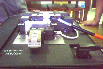
140MBPS Optical Fiber System

Fig. 9: An Image of Installed Fiber Optical System In slot of CPU
|
PDH
system
|
Operating
wave length
|
No: of
E1s
|
|
8
34
140
|
1310nm
1310nm
1310nm
|
4
16
64
|

|
Trans-power
|
– 3dBm
|
|
Minimim power at the receiver (for its
proper working without alarm)
|
-34dBm
|
|
The maximum input power at receiver
the without alarm (for its proper
working without alarm)
|
8dBm
|
Rise Time Budget
|
Component
|
Rise time
|
Worst case value
|
|
MLM Laser diode (ts)
|
0.1-1.0 ns
|
1 ns
|
|
G 652 fibre (tf)
|
< 3.5 ps/km
|
0.05
|
|
APD receiver (tr)
|
< 0.14 ns
|
0.14
|
Filed Under: Articles

Questions related to this article?
👉Ask and discuss on Electro-Tech-Online.com and EDAboard.com forums.
Tell Us What You Think!!
You must be logged in to post a comment.