Mobile overcharging or Laptop overcharging are common problems. People plug in their laptop or mobile for charging overnight which unintentionally leads to overcharging of the device and reducing the battery life. This project allows avoiding overcharging by letting the user set a timer for charging the device. Apart from this home-based application, the project can also be used in industry environment where over-heating of machines has to be avoided by automating the time of their operations.This idea was suggested by Jaya Prakash.

Fig. 1: Prototype of Arduino and RTC DS1307 based Overcharging Protector
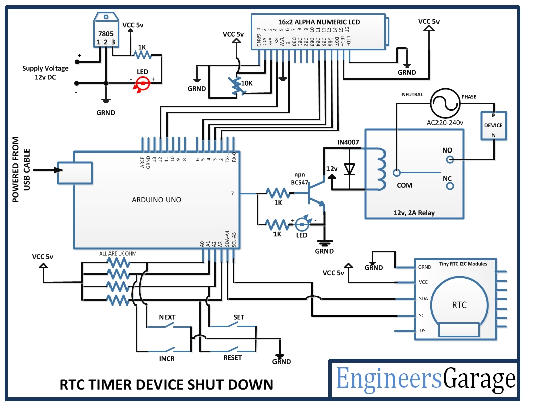
This project implements this application by switching off a connected device to the circuit according to a user defined timer. The project is built on an Arduino UNO Board and utilizes RTC for tracking real time and a relay circuit to implement switching off power supply. The human interface is provided via LCD display and 4-switch keypad is used to feed timer input to the system. Any device running or charging on 230V AC can be programmatically switched off just by connecting the device to the supply via this project.
The project works in the following manner -:
1) The device will be initially cut short of the power supply as it is connected via circuit.
2) The Arduino based circuit will show the current time on the LCD display with the help of RTC.
3) As the user will set time in the circuit, a timer will get activated and power supply to the device will be switched on.
4) The timer can be set by a keypad of four switches – SET Switch to initiate setting process, INCREASE switch to increase hour or minute value of the timer, NEXT switch to skip hours setting to the minutes setting and a RESET switch to reset timer.
5) The current time will be tracked using the RTC and compared with the user defined time to initiate switching off operation.
6) As the current time equates to the user defined time, the circuit will operate the relay to switch off the power supply.
Components Required -:
BLOCK DIAGRAM

Fig. 2: Block Diagram of Arduino and RTC DS1307 based Overcharging Protector
Circuit Connection
| LCD | Arduino UNO |
|---|---|
| RS | 12 |
| RW | GRND |
| E | 11 |
| D7,D6,D5,D4 | 2,3,4,5 respectively |
The standard code library for interfacing Arduino UNO and Arduino Pro Mini are used in the project to program LCD with the board. The code library works as expected. Learn more about LCD interfacing with the Arduino UNO.
| SWITCHES | Arduino UNO |
|---|---|
| SW1(NEXT) | A0 |
| SW2(INC) | A1 |
| SW3(SET) | A2 |
| SW4(RESET) | A3 |
How the Circuit Works -:
Programming Guide
The code utilizes standard libraries of the Arduino UNO. Therefore, first of all predefined libraries for RTC, internal EEPROM and LCD are imported in the code.

Fig. 3: Screenshot of Initialization in Arduino Code for Overcharging Protector
After importing libraries in the code, predefined functions of the standard libraries are used to initialize LCD and RTC. The pinMode() and digitalWrite() functions are used to set the input/output mode and pin status of the Arduino IC pins. An initial message is flashed on the display screen and RTC is tested to fetch current date and time. A HIGH signal at relay pin ensures that the device is cut short of power supply.

Fig. 4: Screenshot of Setup Function in Arduino Code for Overcharging Protector
The current date and time are saved in the internal EEPROM.

Fig. 5: Screenshot of EEPROM related Arduino Code for Overcharging Protector
The current date and time are displayed on 16X2 LCD using predefined functions.

Fig. 6: Screenshot of LCD related Arduino Code for Overcharging Protector
When user enters time through keypad the LCD display goes in timer setting mode. The user entered time is saved to the internal memory (EEPROM) and power supply to the device is switched on by setting pin 7 at HIGH signal. The current time is continuously checked and compared to the user-defined time. As the two matches, the board writes a LOW signal at the pin 7 connected to the relay thereof cutting the power supply to the device.

Fig. 7: Screenshot of checkTime Function in Arduino Code for Overcharging Protector
Project Source Code
###

//Program to

#include <Wire.h>

#include<EEPROM.h>
#include <RTClib.h>
#include <LiquidCrystal.h>
LiquidCrystal lcd(12, 11, 5, 4, 3, 2);
RTC_DS1307 RTC;
int temp,inc,hours1,minut,add=11;
int NEXT=A0;
int INC=A1;
int SET=A2;
int RESET=A3;
int a=0;
int Dstat=0;
#define relay 7
int HOUR,MINUT,SECOND;

void setup()
{
   Wire.begin();
   RTC.begin();
   lcd.begin(16,2);
   pinMode(INC, INPUT);
   pinMode(NEXT, INPUT);
   pinMode(SET, INPUT);
   pinMode(relay, OUTPUT);
   digitalWrite(NEXT, HIGH);
   digitalWrite(SET, HIGH);
   digitalWrite(INC, HIGH);
   digitalWrite(RESET, HIGH);
   digitalWrite(relay,LOW);
   lcd.setCursor(0,0);
   lcd.print("Engineers Garage");
   lcd.setCursor(0,1);
   lcd.print("Real Time Clock");
   delay(3000);
if(!RTC.isrunning())
{
RTC.adjust(DateTime(__DATE__,__TIME__));
}

}

void loop()
{
    int temp=0,val=1,temp4;
   DateTime now = RTC.now();
   if(digitalRead(SET) == 0)      //set Alarm time
   {
     lcd.setCursor(0,0);
     lcd.print("    Set Alarm     ");
    delay(2000);
    time();
    delay(1000);
    lcd.clear();
    lcd.setCursor(0,0);
    lcd.print(" ALARM TIME SET ");
    digitalWrite(relay,HIGH);
     lcd.setCursor(4,1);
     lcd.print(HOUR=hours1,DEC);
     lcd.print(":");
     lcd.print(MINUT=minut,DEC);
     lcd.print(":");
     lcd.print(SECOND=now.second(),DEC);
    Dstat=1;
    delay(2000);
}
if(digitalRead(RESET) == 0)      //set Alarm time
   {
     lcd.setCursor(0,0);
     lcd.print("  Reset Alarm  ");
     delay(2000);
      hours1=0;
      minut=0;
      add=11;
      digitalWrite(relay,LOW);
      delay(2000);
}
checkTime();
lcd.clear();
lcd.setCursor(0,0);
lcd.print("TIME:");
lcd.setCursor(6,0);
lcd.print(HOUR=now.hour(),DEC);
lcd.print(":");
lcd.print(MINUT=now.minute(),DEC);
lcd.print(":");
lcd.print(SECOND=now.second(),DEC);
lcd.setCursor(0,1);
lcd.print(now.day(),DEC);
lcd.print("/");
lcd.print(now.month(),DEC);
lcd.print("/");
lcd.print(now.year(),DEC);
lcd.setCursor(11,1);
lcd.print("T:  ");
lcd.setCursor(13,1);

 }

/*Function to set alarm time and feed time into Internal eeprom*/
void time()
{
  int temp=1,minuts=0,hours=0,seconds=0;
    while(temp==1)
    {
     if(digitalRead(INC)==0)
     {
      HOUR++;
      if(HOUR==24)
      {
       HOUR=0;
      }
      while(digitalRead(INC)==0);
     }
     lcd.clear();
     lcd.setCursor(0,0);
     lcd.print("Set Alarm Time ");
   //lcd.print(x);
    lcd.setCursor(0,1);
    lcd.print(HOUR);
    lcd.print(":");
    lcd.print(MINUT);
    lcd.print(":");
    lcd.print(SECOND);
    delay(100);
    if(digitalRead(NEXT)==0)
    {
      hours1=HOUR;
      EEPROM.write(add++,hours1);
     temp=2;
     while(digitalRead(NEXT)==0);
    }
    }

    while(temp==2)
    {
     if(digitalRead(INC)==0)
     {
      MINUT++;
      if(MINUT==60)
      {MINUT=0;}
      while(digitalRead(INC)==0);
     }
     // lcd.clear();
    lcd.setCursor(0,1);
    lcd.print(HOUR);
    lcd.print(":");
    lcd.print(MINUT);
    lcd.print(":");
    lcd.print(SECOND);
    delay(100);
      if(digitalRead(NEXT)==0)
      {
       minut=MINUT;
       EEPROM.write(add++, minut);
       temp=0;
       while(digitalRead(NEXT)==0);
      }

    }
    delay(1000);
}
/* Function to check time with the user entered time */
void checkTime()
{
  int tem[17];
  for(int i=11;i<17;i++)
  {
    tem[i]=EEPROM.read(i);
  }
  if(HOUR == tem[11] && MINUT == tem[12])
  {
   digitalWrite(relay,LOW);
   hours1=0;
    minut=0;
    Dstat=0;
    add=11;
   }


}

###
Circuit Diagrams
Project Video
Filed Under: Electronic Projects
Filed Under: Electronic Projects

Questions related to this article?
👉Ask and discuss on EDAboard.com and Electro-Tech-Online.com forums.
Tell Us What You Think!!
You must be logged in to post a comment.