Summary of the circuit-
-
Lots of conditions arrive in one’s life where he/she gets panicked.
-
This may be due to the bad health or an intrusion of some unknown person inside the house.
-
So here is one project i.e. a panic alarm that will help you to let others know that you are in some bad situation and need their help.
-
At the time when you need someone’s help, just press the switch in the circuit and a sound will generate..
-
This circuit is made up of NE555 timer connected in astable mode..
Principle behind Circuit-
This circuit costs too less to your pocket as it made up of NE555 IC, buzzer, some resistors and capacitors. This circuit is also user friendly. As with the help of just a press on the button you will let others know that you are in panicking condition without any difficulty.
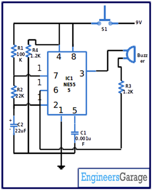
In this project astable mode of IC NE555 is used. Resistors R1 and R2 along with capacitor C2 have been used in the circuit so as to tune the frequency. In the starting, the circuit remains in the disabled state. Now when the button is pressed the pin 4 and pin 8 of IC1 get the high voltage. In turn the voltage at pin 2 goes down gradually and voltage at pin 3 starts increasing in the same manner. And a situation arrives when the sound comes out from the buzzer.
The circuit uses 9V of power supply to work. You can also use some sound circuit in place of buzzer. LED can be used in the circuit to provide a visualized signal.
Components required building the circuit-
IC
IC1 NE555
Resistor
R1 100K
R2 22K
R3 1.2K
R4 1.2K
Capacitor
C1 0.001uF
C2 22uF
Switch
S1 push-to-on
Buzzer
Power Supply 6V-12V

Fig. 1: Prototype of 555 IC based Panic Alarm Circuit
Circuit Diagrams
Project Video
Filed Under: Electronic Projects
Filed Under: Electronic Projects

Questions related to this article?
👉Ask and discuss on EDAboard.com and Electro-Tech-Online.com forums.
Tell Us What You Think!!
You must be logged in to post a comment.